
Page 434 - Subyek Computer Aided Design - [David Planchard] Engineering Design with SOLIDWORKS
P. 434
Extrude and Revolve Features Engineering Design with SOLIDWORKS® 2018
Add a Perpendicular relation.
519) Click the left V shape line.
520) Hold the Ctrl key down.
•
521) Click the right V shape line. The Properties I
PropertyManager is displayed. d i l
I i JI)
•
522) Release the Ctrl key. I
•
~
L
523) Click Perpendicular .L from the Add Relations box. •
524) Click OK ef from the Properties PropertyManager.
The sketch is fully defined.
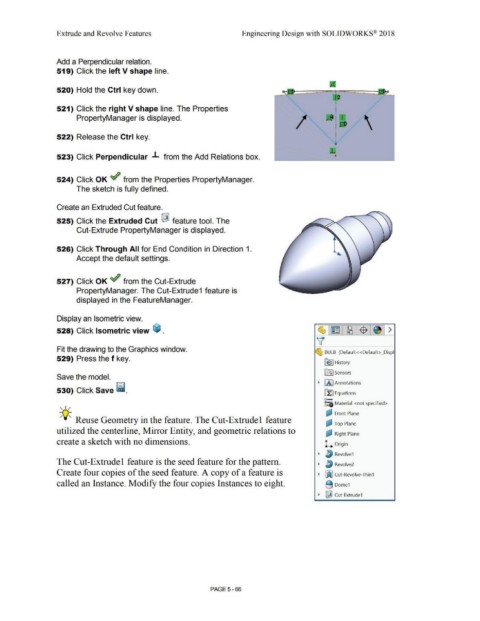
Create an Extruded Cut feature.
525) Click the Extruded Cut ~ feature tool. The
Cut-Extrude PropertyManager is displayed.
526) Click Through All for End Condition in Direction 1.
Accept the default settings.
527) Click OK ef from the Cut-Extrude
PropertyManager. The Cut-Extrude1 feature is
displayed in the FeatureManager.
Display an Isometric view.
528) Click Isometric view ~ .
Fit the drawing to the Graphics window.
~ BULB (Default<<Default> _Displ
529) Press the f key.
~ I History
ifl:J Sensors
Save the model.
~ fA I Annotations
530) Click Save ii.
~ Equations
o-
~:a Material <not specified>
, 1 /
(J.,I Front Plane
-,Q~ Reuse Geometry in the feature. The Cut-Extrudel feature I
~ Top Plane
utilized the centerline, Mirror Entity, and geometric relations to a- Right Plane
I
create a sketch with no dimensions. L Origin
~ ~ Revolve1
The Cut-Extrudel feature is the seed feature for the pattern. ~ J/j Revolve2
Create four copies of the seed feature. A copy of a feature is ~ ~ Cut-Revolve-Thin1
called an Instance. Modify the four copies Instances to eight. B Dome1
~ ~ Cut-Extrude1
PAGE 5-66