
Page 430 - Subyek Computer Aided Design - [David Planchard] Engineering Design with SOLIDWORKS
P. 430
Extrude and Revolve Features Engineering Design with SOLIDWORKS® 2018
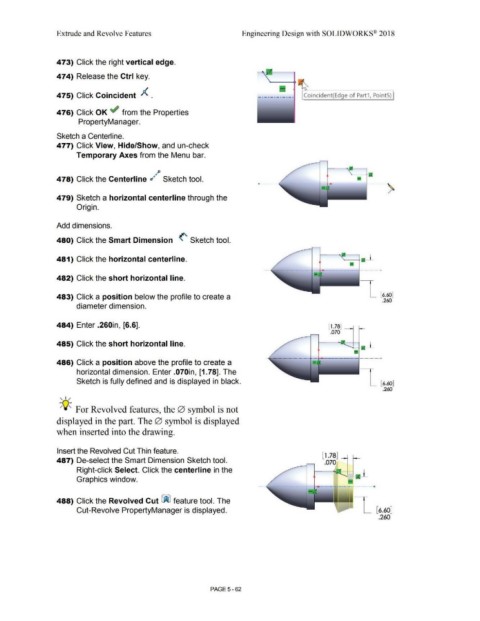
473) Click the right vertical edge.
474) Release the Ctrl key.
475) Click Coincident A . Coincident(Edge of Part1, PointS)
476) Click OK ~ from the Properties
PropertyManager.
Sketch a Centerline.
477) Click View, Hide/Show, and un-check
Temporary Axes from the Menu bar.
~p
478) Click the Centerline d ~ Sketch tool. -- -------·,
- -------
/
479) Sketch a horizontal centerline through the
Origin.
Add dimensions.
480) Click the Smart Dimension (' Sketch tool.
481) Click the horizontal centerline.
•
·- ·-·--l-·-·-·-·--
482) Click the short horizontal line.
483) Click a position below the profile to create a [6.60]
.260
diameter dimension.
484) Enter .260in, [6.6]. ll .78J -
.070
485) Click the short horizontal line.
486) Click a position above the profile to create a
horizontal dimension. Enter .070in, [1. 78]. The
Sketch is fully defined and is displayed in black. [6.60]
.260
, ,/
-;Q~ For Revolved features, the 0 symbol is not
displayed in the part. The 0 symbol is displayed
when inserted into the drawing.
Insert the Revolved Cut Thin feature.
l 1.78 J
487) De-select the Smart Dimension Sketch tool. .070
Right-click Select. Click the centerline in the 1-a-l
Graphics window.
488) Click the Revolved Cut ~ feature tool. The
Cut-Revolve PropertyManager is displayed. [6.60]
.260
PAGE5 - 62