
Page 421 - Subyek Computer Aided Design - [David Planchard] Engineering Design with SOLIDWORKS
P. 421
Engineering Design with SOLIDWORKS® 2018 Extrude and Revolve Features
I Activity: LENS Part - Extruded Boss Feature and Offset Entities
Create the Sketch.
374) Click Isometric view ~ from the Heads-up View
tool bar.
~ ~ ~ i e +, ~ T ~
~~ I~ fe> J> (B (tJ
375) Click Hidden Lines Removed GJ from the Heads-up
View toolbar. Sketch Tools •
Zoom/Pan/Rotate •
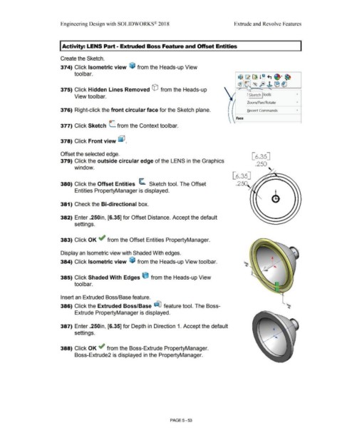
376) Right-click the front circular face for the Sketch plane. Recent Commands •
Face
J)-
377) Click Sketch L from the Context toolbar.
378) Click Front view ~ .
Offset the selected edge. [6.35]
379) Click the outside circular edge of the LENS in the Graphics
.250
window.
[6.35]
380) Click the Offset Entities ~ Sketch tool. The Offset .250
Entities PropertyManager is displayed.
381) Check the Bi-directional box.
382) Enter .250in, [6.35] for Offset Distance. Accept the default
settings.
383) Click OK ~ from the Offset Entities PropertyManager.
Display an Isometric view with Shaded With edges.
384) Click Isometric view ~ from the Heads-up View toolbar.
385) Click Shaded With Edges e from the Heads-up View
tool bar.
Insert an Extruded Boss/Base feature.
386) Click the Extruded Boss/Base ~ feature tool. The Boss-
Extrude PropertyManager is displayed.
387) Enter .250in, [6.35] for Depth in Direction 1. Accept the default
settings.
388) Click OK ~ from the Boss-Extrude PropertyManager.
Boss-Extrude2 is displayed in the PropertyManager.
PAGE 5 - 53