
Page 420 - Subyek Computer Aided Design - [David Planchard] Engineering Design with SOLIDWORKS
P. 420
Extrude and Revolve Features Engineering Design with SOLIDWORKS® 2018
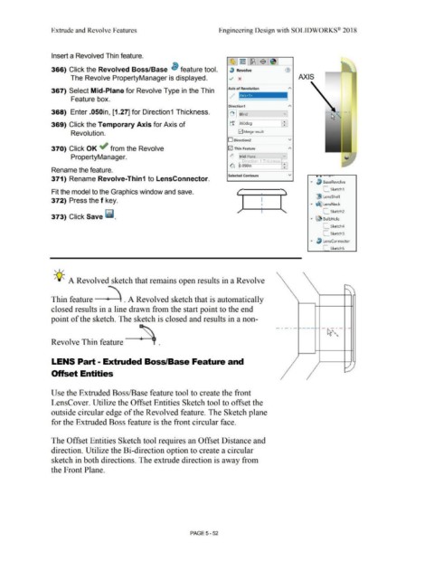
Insert a Revolved Thin feature.
366) Click the Revolved Boss/Base ~ feature tool. 3 Revolve
The Revolve PropertyManager is displayed. v x AXIS
367) Select Mid-Plane for Revolve Type in the Thin Axis of Revolution ---
-
--
Feature box. 1
Direction1
368) Enter .050in, [1.27] for Direction1 Thickness. I~ I ~:Bli~nd ____ ~v]
369) Click the Temporary Axis for Axis of tr 360deg ~
Revolution. E2I Merge result
O Direction2 v
370) Click OK ~ from the Revolve E2I Thin Feature A
PropertyManager. ~ Mid-Plane v
~ Direction 1 Thickness
~ p.oso,n :
Rename the feature.
Select.ed Contours v ....... ..,
371) Rename Revolve-Thin1 to LensConnector.
... ~ BaseRevolve
Fit the model to the Graphics window and save. L_ Sketch1
l!ll LensShell
372) Press the f key.
... ~ LensNeck
L_ Sketch2
373) Click Save ~ .
"" ~ BulbHole
L_ Sketch4
C_ Sketch3
... ~ LensConnector
-
SketchS
, 1,,
-;Q~ A Revolved sketch that remains open results in a Revolve
Thin feature . A Revolved sketch that is automatically
closed results in a line drawn from the start point to the end
point of the sketch. The sketch is closed and results in a non-
Revolve Thin feature •
LENS Part - Extruded Boss/Base Feature and
Offset Entities
Use the Extruded Boss/Base feature tool to create the front
LensCover. Utilize the Offset Entities Sketch tool to offset the
outside circular edge of the Revolved feature. The Sketch plane
for the Extruded Boss feature is the front circular face.
The Offset Entities Sketch tool requires an Offset Distance and
direction. Utilize the Bi-direction option to create a circular
sketch in both directions. The extrude direction is away from
the Front Plane.
PAGE5-52