
Page 480 - Subyek Computer Aided Design - [David Planchard] Engineering Design with SOLIDWORKS
P. 480
Swept, Lofted and Additional Features Engineering Design with SOLIDWORKS® 2018
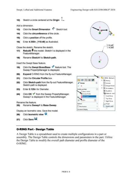
Sketch a circle centered at the Origin L.
12)
Add a dimension.
13) Click the Smart Dimension (' Sketch tool.
14) Click the circumference of the circle.
;(
15) Click a position off the profile.
16) Enter 4.350in, [110.49] as illustrated.
~[110.49]
Close the sketch. Rename the sketch. ~ 4.350
17) Rebuild I the model. Sketch1 is displayed in the
FeatureManager.
L
18) Rename Sketch1 to Sketch-path.
Insert the Swept Base feature.
19) Click the Swept Boss/Base r/J feature tool. The
Sweep PropertyManager is displayed.
20) Expand 0-RING from the fly-out FeatureManager.
I
!) ....
21) Click the Circular Profile box. ~ 0 -RING (Default<
~ E l-l!B 1$ 1 ~ RY I History
22) Click Sketch-path from the fly-out FeatureManager. ./> Sweep G) in:J Sensors
Sketch-path is displayed. ../ x ~ [DJ Design Binder
~ ~ I Annotations
23) Enter 0.125in for Diameter. Profile and Path El
i'.fl Equations
O Sketch Profile
o-
24) Click OK ~ from the Sweep PropertyManager. ::;a Material <not
[P Front Plane
Sweep1 is displayed in the FeatureManager.
cP Top Plane
...
0 . 12Sin ...
[P Right Plane
Rename the feature.
Options v L Origin
25) Rename Sweep1 to Base-Sweep.
D Thin Feature v IC ~ etch-path!
Curvature Display v
Display an Isometric view. Save the model. ""
26) Click Isometric view ~ .
27) Click Save llm.
0-RING Part - Design Table
A Design Table is a spreadsheet used to create multiple configurations in a part or
assembly. The Design Table controls the dimensions and parameters in the part. Utilize
the Design Table to modify the overall path diameter and profile diameter of the
0-RING.
PAGE6 - 8