Page 484 - Subyek Computer Aided Design - [David Planchard] Engineering Design with SOLIDWORKS
P. 484

Swept, Lofted and Additional Features                                                                                                                      Engineering Design with SOLIDWORKS® 2018


                                                   , 1 /


                                                  ;Q~ The Sketch toolbar contains two areas: Sketch Entities and Sketch Tools. There are


                                                numerous ways to access these areas: Select the Sketch (_ icon from the Sketch toolbar,


                                                right-click and select the Sketch icon from the Context toolbar or click Tools, Sketch


                                                Entities or Sketch Tools from the Menu bar.


                                                SWITCH Part-Lofted Base Feature                                                                                                                                                                                                               ....  ~ SWITCH  (Default< ...


                                                                                                                                                                                                                                                                                                     ~  re I History


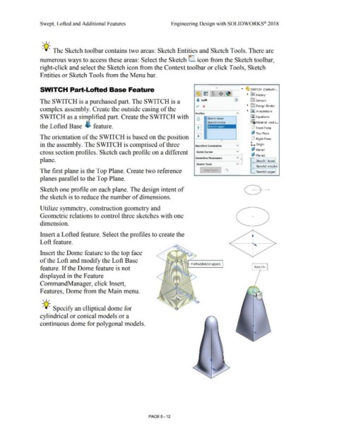
                                                The SWITCH is a purchased part. The SWITCH is a                                                                                                                                                                                                          ffiJ Sensors

                                                                                                                                                                                                                                        v  x                                                         ~  uIJ Design Binder
                                                complex assembly. Create the outside casing of the                                                                                                                                                                                                   ~  iAJ Annotations


                                                                                                                                                                                                                                        Profiles
                                                SWITCH as a simplified part. Create the SWITCH with                                                                                                                                       0                                                              il!J Equations

                                                                                                                                                                                                                                         <>           Sketch1-lower                                      o-
                                                                                                                                                                                                                                                                                                         ~=6 Material  < not s ...
                                                the Lofted Base i  feature.                                                                                                                                                            l1l                                                                (!:I  Front Plane


                                                The orientation of the SWITCH is based on the position  0                                                                                                                                                                                                 ~ Top Plane

                                                                                                                                                                                                                                                                                                          (!:I  Right Plane


                                                in the assembly. The SWITCH is comprised of three                                                                                                                                       Start/End Constraints                           v                L     origin


                                                                                                                                                                                                                                                                                                          ~ Plane1
                                                cross section profiles. Sketch each profile on a different                                                                                                                               Guide Curves                                   v

                                                                                                                                                                                                                                                                                                            •  Plane2
                                                plane.                                                                                                                                                                                  Centerline Parameters                           v  ,.,           L.. Sketch 1-lower


                                                                                                                                                                                                                                         Sketch Tools
                                                                                                                                                                                                                                                                                                         L.. Sketch2-middle
                                                The first plane is the Top Plane. Create two reference                                                                                                                                            or.igskttch                                            L.. Sketch3-uooer

                                                                                                                                                                                                                                      .._ _____ ___.__ ____ ____.

                                                planes parallel to the Top Plane.


                                                Sketch one profile on each plane. The design intent of


                                                the sketch is to reduce the number of dimensions.


                                                Utilize symmetry, construction geometry and


                                                Geometric relations to control three sketches with one                                                                                                                                                                                                     +


                                                dimension.


                                                Insert a Lofted feature. Select the profiles to create the


                                                Loft feature.


                                                Insert the Dome feature to the top face


                                                of the Loft and modify the Loft Base


                                                                                                                                                                                                                                  Profile(Sketch3-upper)
                                                feature. If the Dome feature is not                                                                                                                                                                                                                           Face<1 >


                                                displayed in the Feature


                                                CommandManager, click Insert,


                                                Features, Dome from the Main menu.


                                                   , 1 /


                                                  ;Q~ Specify an elliptical dome for


                                                cylindrical or conical models or a


                                                continuous dome for polygonal models.


                                                                                                                                                                                PAGE6 - 12
   479   480   481   482   483   484   485   486   487   488   489