
Page 486 - Subyek Computer Aided Design - [David Planchard] Engineering Design with SOLIDWORKS
P. 486
Swept, Lofted and Additional Features Engineering Design with SOLIDWORKS® 2018
Display a Top view.
69) Click Top view
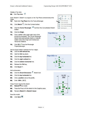
Insert Sketch1. Sketch1 is a square on the Top Plane centered about the
Origin.
70) Right-click Top Plane from the FeatureManager. O Corner Rectangle
Center Rectangle
71) Click Sketch (_ from the Context toolbar. <>, 3 Point Corner Rectangle
, <e}, 3 Point Center Rectangle
72) Click the Center Rectangle G tool from the Consolidated Sketch il Parallelogram
tool bar.
73) Click the Origin.
74) Click a point in the upper right hand of the
window as illustrated. The Center Rectangle ' '\.
'
Sketch tool automatically inserts a midpoint '\.
'
relation about the Origin and Vertical and
Horizontal relations.
75) Click OK ~ from the Rectangle
PropertyManager.
Add an Equal relation between the four edges.
76) Click the left vertical line.
77) Hold the Ctrl key down.
78) Click the top horizontal line.
79) Click the right vertical line. '
• /
'
80) Click the bottom horizontal line. '
81) Release the Ctrl key.
' '
82) Click Equal = .
Add a dimension.
83) Click the Smart Dimension (' Sketch tool.
84) Click the top horizontal line. [ 12.70]
85) Click a position above the profile. .500
86) Enter .500in, [12.7].
Close, fit and rename the sketch. /
'
/
87) Rebuild I the model. ' ,
88) Press the f key to fit the sketch to the Graphics area.
'
'\..
89) Rename Sketch1 to Sketch1-lower. ' '\..
' ' '\..
Save the model.
90) Click Save ii.
PAGE 6 - 14