Page 489 - Subyek Computer Aided Design - [David Planchard] Engineering Design with SOLIDWORKS
P. 489

Engineering Design with SOLIDWORKS® 2018                                                                                                                                             Swept, Lofted and Additional Features


                                                                        The system displays a preview curve and loft as you select the                                                                                                                                                       Profiles

                                                                                                                                                                                                                                                                                                         n , .............................................................................  "'
                                                                       profiles. Use the Up button and Down button in the Loft                                                                                                                                                                 <>             Sketchl -lower                              1
                                                                                                                                                                                                                                                                                                0
                                                                                                                                                                                                                                                                                                              : ............................................................................ ;
                                                                                                                                                                                                                                                                                                              Sketch2-middle
                                                                        Property Manager to rearrange the order of the profiles.                                                                                                                                                             [!]              Sketch3-upper


                                                                          , ,/                                                                                                                                                                                                                                    ~
                                                                                                                                                                                                                                                                                             IT]         --                  Clear Selections


                                                                          -;Q~ Redefine incorrect selections efficiently. Right-click in the                                                                                                                                                                                 SelectionManager


                                                                        Graphics window, and click Clear Selections to remove selected                                                                                                                                                       Start/End C                     Customize Menu


                                                                       profiles. Select the correct profiles.


                                                                        SWITCH Part - Dome Feature


                                                                        Insert the Dome feature on the top face of the Lofted Base feature. The Dome feature


                                                                        forms the top surface of the SWITCH. Note: You can specify an elliptical dome for


                                                                        cylindrical or conical models and a continuous dome for polygonal models. A continuous


                                                                        dome's shape slopes upwards, evenly on all sides.


                                                                       I Activity: SWITCH Part - Dome Feature


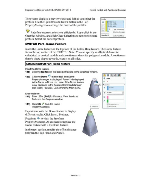
                                                                        Insert the Dome feature.


                                                                        128)  Click the top face of the Base Loft feature in the Graphics window.


                                                                                                                                                                                                                                                                                                   ~ E~ $ ~
                                                                        129)  Click the Dome 8  feature tool. The Dome


                                                                                                                                                                                                                                                                                                   B  Dome                                                (1)
                                                                                           PropertyManager is displayed. Face<1 > is displayed


                                                                                           in the Faces to Dome box. Note: If the Dome feature


                                                                                          is not displayed in the Feature CommandManager,                                                                                                                                                         Parameters                                                 "'


                                                                                           click Insert, Features, Dome from the Main menu.


                                                                                                                                                                                                                                                                                                                                                      -
                                                                                                                                                                                                                                                                                                                                                      • •
                                                                        Enter distance.                                                                                                                                                                                                          ~ ,_0.200in                                            •


                                                                        130)  Enter .20in, [5.08] for Distance. View the dome                                                                                                                                                                      ct I.I


                                                                                          feature in the Graphics window.                                                                                                                                                                                       :=======:


                                                                        131)  Click OK ~ from the Dome                                                                                                                                                                                                      [21 Continuous dome


                                                                                           PropertyManager.                                                                                                                                                   f Face< 1 >  I                                [21 Show preview


                                                                        Experiment with the Dome feature to display


                                                                        different results. Click Insert, Features,


                                                                        Freeform  e, to view the Freeform


                                                                        PropertyManager. As an exercise replace the


                                                                       Dome feature with a Freeform feature.


                                                                        In the next section, modify the offset distance


                                                                       between the Top Plane and Plane  1.


                                                                                                                                                                                                        PAGE6 - 17
   484   485   486   487   488   489   490   491   492   493   494