
Page 492 - Subyek Computer Aided Design - [David Planchard] Engineering Design with SOLIDWORKS
P. 492
Swept, Lofted and Additional Features Engineering Design with SOLIDWORKS® 2018
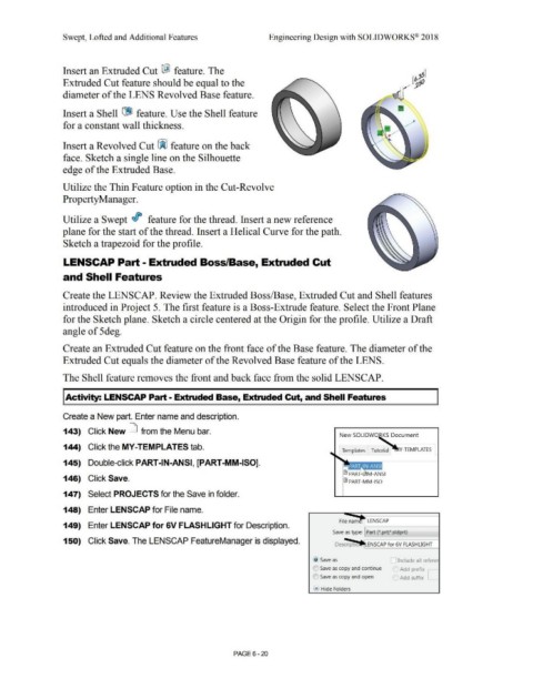
Insert an Extruded Cut I@ feature. The
Extruded Cut feature should be equal to the
diameter of the LENS Revolved Base feature.
Insert a Shell [19] feature. Use the Shell feature
for a constant wall thickness.
Insert a Revolved Cut ~ feature on the back
face. Sketch a single line on the Silhouette
edge of the Extruded Base.
Utilize the Thin Feature option in the Cut-Revolve
Property Manager.
Utilize a Swept If feature for the thread. Insert a new reference
plane for the start of the thread. Insert a Helical Curve for the path.
Sketch a trapezoid for the profile.
LENSCAP Part - Extruded Boss/Base, Extruded Cut
and Shell Features
Create the LENSCAP. Review the Extruded Boss/Base, Extruded Cut and Shell features
introduced in Project 5. The first feature is a Boss-Extrude feature. Select the Front Plane
for the Sketch plane. Sketch a circle centered at the Origin for the profile. Utilize a Draft
angle of 5deg.
Create an Extruded Cut feature on the front face of the Base feature. The diameter of the
Extruded Cut equals the diameter of the Revolved Base feature of the LENS.
The Shell feature removes the front and back face from the solid LENSCAP.
!Activity: LENSCAP Part- Extruded Base, Extruded Cut, and Shell Features
Create a New part. Enter name and description.
143) Click New D from the Menu bar.
New SOLIDWO KS Document
144) Click the MY-TEMPLATES tab.
Templates Tutorial Y-TEMPLATES
145) Double-click PART-IN-ANSI, [PART-MM-ISO].
~ PAR M-ANSI
146) Click Save.
~ PART-MM-ISO
147) Select PROJECTS for the Save in folder.
148) Enter LENSCAP for File name.
149) Enter LENSCAP for 6V FLASHLIGHT for Description.
Save as type: Part (*.prt;*.sldprt)
150) Click Save. The LENSCAP FeatureManager is displayed.
~> Save as [l Include all refere
(0 Save as copy and continue Add prefix [_
(C) Save as copy and open ( Add suffix
... Hide Folders
PAGE6 - 20