
Page 495 - Subyek Computer Aided Design - [David Planchard] Engineering Design with SOLIDWORKS
P. 495
Engineering Design with SOLIDWORKS® 2018 Swept, Lofted and Additional Features
LENSCAP Part - Revolved Thin Cut Feature
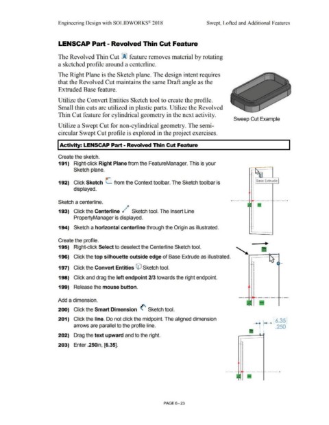
The Revolved Thin Cut ~ feature removes material by rotating
a sketched profile around a centerline.
The Right Plane is the Sketch plane. The design intent requires
that the Revolved Cut maintains the same Draft angle as the
Extruded Base feature.
Utilize the Convert Entities Sketch tool to create the profile.
Small thin cuts are utilized in plastic parts. Utilize the Revolved
Thin Cut feature for cylindrical geometry in the next activity.
Sweep Cut Example
Utilize a Swept Cut for non-cylindrical geometry. The semi-
circular Swept Cut profile is explored in the project exercises.
I Activity: LENSCAP Part - Revolved Thin Cut Feature
Create the sketch.
191) Right-click Right Plane from the FeatureManager. This is your
Sketch plane. r···~ ·-············
0-
192) Click Sketch L from the Context toolbar. The Sketch toolbar is
displayed. I
- ----- : ------- -----·
Sketch a centerline.
•p
193) Click the Centerline r1· Sketch tool. The Insert Line
PropertyManager is displayed.
194) Sketch a horizontal centerline through the Origin as illustrated.
Create the profile.
195) Right-click Select to deselect the Centerline Sketch tool.
196) Click the top silhouette outside edge of Base Extrude as illustrated. ,-·----·-------
197) Click the Convert Entities CO Sketch tool.
198) Click and drag the left endpoint 2/3 towards the right endpoint.
199) Release the mouse button.
-----IH· ----·-· --·
Add a dimension.
200) Click the Smart Dimension (' Sketch tool.
201) Click the line. Do not click the midpoint. The aligned dimension _. [ 6.35]
arrows are parallel to the profile line. .250
202) Drag the text upward and to the right. a o
203) Enter .250in, [6.35].
---- ------- -----·
PAGE 6-23