
Page 494 - Subyek Computer Aided Design - [David Planchard] Engineering Design with SOLIDWORKS
P. 494
Swept, Lofted and Additional Features Engineering Design with SOLIDWORKS® 2018
Insert an Extruded Cut feature.
Direction 1
174) Click the Extruded Cut [&! feature
~ .__:s,_ind ____ __.v I
tool. The Cut-Extrude
PropertyManager is displayed. 74
Blind is the default End Condition.
175) Enter .275in, [6.99] for Depth in ~ [o.27Sin [:]
Direction 1 . D Flip side to cut
176) Click the Draft On/Off button. ~ jL--sde_g ----------=ffi===": I
D Draft outward
177) Enter 5deg for Angle. Accept the default settings.
~·~ ltcB l$ l~I
178) Click OK .; from the Cut-Extrude
(l!9 Shell 1 (1)
PropertyManager. Cut-Extrude1 is displayed in
v x
the FeatureManager.
Parameters I h. k l I Aj
. T 1c ness .
179) Rename Cut-Extrude1 to Front-Cut. G o.,soi k:
Insert the Shell feature.
180) Click the Shell ['.j9 feature tool. The Shell1
PropertyManager is displayed. t)
D Shell outward
181) Click the front face of the Front-Cut as D Show preview
illustrated. Multi-thickness Settings A
G lo.1ooin Ff
182) Press the left arrow approximately 8 times to
~
view the back face.
183) Click the back face of the Base Extrude.
184) Enter .150in, [3.81] for Thickness.
185) Click OK .; from the Shell 1 PropertyManager. Shell 1 is displayed in
the FeatureManager.
Display an Isometric view.
186) Press the space bar to display the Orientation dialog box.
187) Click Isometric view ~ .
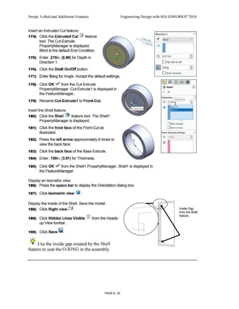
Display the inside of the Shell. Save the model.
188) Click Right view @. Inside Gap
from the Shell
feature.
189) Click Hidden Lines Visible ® from the Heads-
up View toolbar.
190) Click Save ii.
, ,/
-;Q;_ Use the inside gap created by the Shell
feature to seat the 0-RING in the assembly.
PAGE6 - 22