
Page 493 - Subyek Computer Aided Design - [David Planchard] Engineering Design with SOLIDWORKS
P. 493
Engineering Design with SOLIDWORKS® 2018 Swept, Lofted and Additional Features
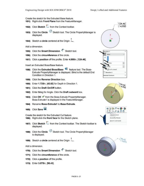
Create the sketch for the Extruded Base feature.
151) Right-click Front Plane from the FeatureManager.
,---[ 124.46]
o-
152) Click Sketch L from the Context toolbar. (/) 4.900
153) Click the Circle 0 Sketch tool. The Circle PropertyManager is
displayed.
154) Sketch a circle centered at the Origin L.
Add a dimension.
155) Click the Smart Dimension (' Sketch tool. Direction 1
~ Blind v
156) Click the circumference of the circle.
157) Click a position off the profile. Enter 4.900in, [124.46].
..
•
Insert an Extruded Boss/Base feature. ]+ '
158) Click the Extruded Boss/Base ~ feature tool. The Boss-
Extrude PropertyManager is displayed. Blind is the default End D Direction 2 v
Condition in Direction 1. Selected Contours v
159) Click the Reverse Direction box.
160) Enter 1.725in, [43.82] for Depth in Direction 1.
161) Click the Draft On/Off button.
162) Enter 5deg for Angle. Click the Draft outward box.
163) Click OK ~ from the Boss-Extrude PropertyManager.
Boss-Extrude1 is displayed in the FeatureManager.
164) Rename Boss-Extrude1 to Base Extrude.
165) Click Save l'i.
Create the sketch for the Extruded Cut feature. Sketch Tools
166) Right-click the front face for the Sketch plane. Zoom/Pan/Rotate
Becent Commands
0-
167) Click Sketch L from the Context toolbar. The Sketch toolbar is Face
displayed.
168) Click the Circle 0 Sketch tool. The Circle PropertyManager
is displayed.
169) Sketch a circle centered at the Origin L.
Add a dimension.
170) Click the Smart Dimension (' Sketch tool.
171) Click the circumference of the circle.
172) Click a position off the profile.
173) Enter 3.875in, [98.43].
PAGE 6 - 21