
Page 497 - Subyek Computer Aided Design - [David Planchard] Engineering Design with SOLIDWORKS
P. 497
Engineering Design with SOLIDWORKS® 2018 Swept, Lofted and Additional Features
I Activity: LENSCAP Part - Thread, Swept Feature, and Helix/Spiral Curve
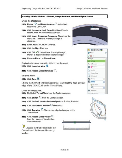
Create the offset plane.
213) Rotate ti and Zoom to Area P on the back
face of the LENS CAP.
214) Click the narrow back face of the Base Extrude
feature. Note the mouse feedback icon.
215) Click Insert, Reference Geometry, Plane from the
Menu bar. The Plane PropertyManager is
displayed.
216) Enter .450in, [11.43] for Distance.
217) Click the Flip offset box.
218) Click OK ~ from the Plane PropertyManager. ~ Plane
Plane1 is displayed in the FeatureManager.
219) Rename Plane1 to ThreadPlane. Message A A
Fully defined
Display the Isometric view with Hidden Lines Removed. First Reference
220) Click Isometric view ~ . (i:l Face<1 >
221) Click Hidden Lines Removed GJ. [~ ] Parallel
[ I J Perpendicular
Save the model. JA J Coincident
222) Click Save !Ii. [tf] 90deg
l~J lo.450in
Utilize the Convert Entities Sketch tool to extract the back circular
Flip offset
edge of the LENS CAP to the ThreadPlane.
Create the Thread path. J J Mid Plane
223) Right-click ThreadPlane from the FeatureManager.
224) Click Sketch (_ from the Context toolbar.
225) Click the back inside circular edge of the Shell as illustrated.
226) Click the Convert Entities © Sketch tool.
227) Click Top view @ . The circular edge is displayed on the
Thread Plane. I
228) Click Hidden Lines Visible ®
Base Extrude
from the Heads-up View toolbar.
View the results.
• •
•
•
, ,/ • •
•
•
•
• •
•
• •
• •
•
•
-;Q~ Access the Plane tool from the : ......--- ·----------- :
•
•
...
.....
Consolidated Reference Geometry
toolbar.
PAGE 6 - 25