
Page 499 - Subyek Computer Aided Design - [David Planchard] Engineering Design with SOLIDWORKS
P. 499
Engineering Design with SOLIDWORKS® 2018 Swept, Lofted and Additional Features
Sketch the profile.
245) Click Sketch L from the Context
tool bar.
r
•
246) Click Top view @] _ I
•
I
•
I
~p
•
247) Click the Centerline d ~ Sketch tool. I
•
t-·
•
I
•
I
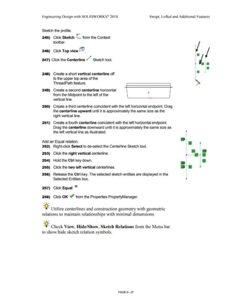
248) Create a short vertical centerline off I
•
•
to the upper top area of the I
ThreadPath feature. ~
.I"
249) Create a second centerline horizontal
from the Midpoint to the left of the
vertical line.
250) Create a third centerline coincident with the left horizontal endpoint. Drag
the centerline upward until it is approximately the same size as the
right vertical line.
251) Create a fourth centerline coincident with the left horizontal endpoint.
Drag the centerline downward until it is approximately the same size as
the left vertical line as illustrated. c
I
I
I
m=ill I
Add an Equal relation. I 11"'11"'1
I ....... i
252) Right-click Select to de-select the Centerline Sketch tool. I •
I I
I •
t--
253) Click the right vertical centerline.
254) Hold the Ctrl key down.
255) Click the two left vertical centerlines.
256) Release the Ctrl key. The selected sketch entities are displayed in the
Selected Entities box.
-
257) Click Equal - .
258) Click OK ~ from the Properties PropertyManager.
, ,/
-;Q~ Utilize centerlines and construction geometry with geometric
relations to maintain relationships with minimal dimensions.
, 1 /
-;Q~ Check View, Hide/Show, Sketch Relations from the Menu bar
to show/hide sketch relation symbols.
PAGE 6 - 27