
Page 500 - Subyek Computer Aided Design - [David Planchard] Engineering Design with SOLIDWORKS
P. 500
Swept, Lofted and Additional Features Engineering Design with SOLIDWORKS® 2018
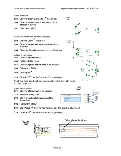
Add a dimension.
[ 12.70]
259) Click the Smart Dimension (' Sketch tool.
.500
260) Click the two left vertical endpoints. Click a
position to the left.
261) Enter .500in, [12.7]. 1
~---------------------· •
j
Sketch the profile. The profile is a trapezoid.
262) Click the Line / Sketch tool. [12.70]
.500
263) Click the endpoints to create the trapezoid as
illustrated.
264) Right-click Select to de-select the Line Sketch tool.
Add an Equal relation.
265) Click the left vertical line. t
266) Hold the Ctrl key down.
267) Click the top and bottom lines of the trapezoid.
268) Release the Ctrl key.
12.701
- .500
269) Click Equal - .
270) Click OK ~ from the Properties PropertyManager.
--l--10
Click and drag the sketch to a position above the top right comer
of the LENSCAP.
[ 12.70]
Add a Pierce relation.
.500
271) Click the left midpoint of the trapezoid.
272) Hold the Ctrl key down.
Selected Entities
I =.2 = ;I
273) Click the starting left back edge of the Edge<l > = I - -- I I
-
Thread Path. Point4
e
274) Release the Ctrl key.
275) Click Pierce <$S from the Add Relations box. The sketch is fully defined.
276) Click OK ~ from the Properties PropertyManager.
Select edge on the left side
[12.70]
.500
. I'-.. •
f I · ! ! -
... -
l
~- , . = 2 =3 I •
-- -
-] I .:..:s -
~· - --. ----
\ ... _ ----------- .. ------
PAGE 6 - 28