
Page 505 - Subyek Computer Aided Design - [David Planchard] Engineering Design with SOLIDWORKS
P. 505
Engineering Design with SOLIDWORKS® 2018 Swept, Lofted and Additional Features
Rename the feature and save the model.
307) Rename Boss-Extrude1 to Base Extrude.
308) Click Save ~ .
HOUSING Part- Lofted Boss Feature
The Lofted Boss feature is composed of two profiles. The first sketch is named Sketch-
Circle. The second sketch is named Sketch-Square.
Create the first profile from the back face of the Extruded feature. Utilize the Convert
Entities sketch tool to extract the circular geometry to the back face.
Create the second profile on an Offset Plane. The FLASHLIGHT components must
remain aligned to a common centerline. Insert dimensions that reference the Origin and
build symmetry into the sketch. Utilize the Mirror Entities Sketch tool.
I Activity: HOUSING Part - Lofted Boss Feature
Create the first profile.
309) Right-click the back face of the Base Extrude feature. This is
your Sketch plane.
o-
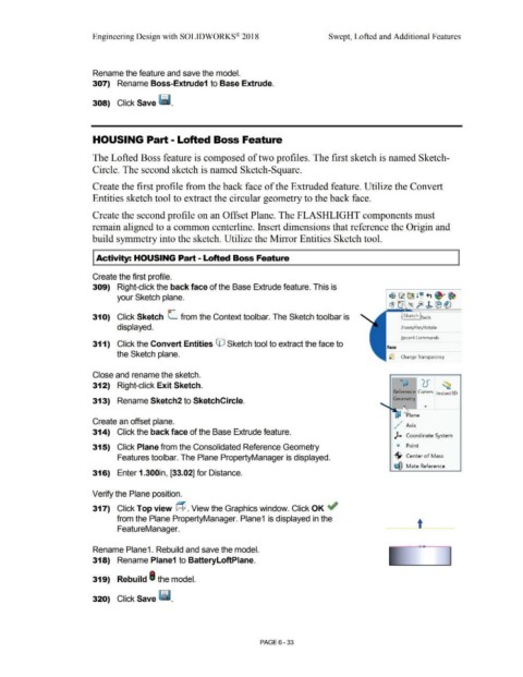
31 O) Click Sketch L from the Context tool bar. The Sketch tool bar is Sketch ools
displayed. Zoom/Pan/Rotate
Becent Commands
311) Click the Convert Entities CO Sketch tool to extract the face to
Face
the Sketch plane. ~ Change Transparency
Close and rename the sketch.
312) Right-click Exit Sketch. o°' ') r ~
'
u
Reference Curves lnstant3D
313) Rename Sketch2 to SketchCircle. Geometry
~ lane •
Create an offset plane. ;
,,./· Axis
314) Click the back face of the Base Extrude feature.
). Coordinate System
315) Click Plane from the Consolidated Reference Geometry ~ Point
Features toolbar. The Plane PropertyManager is displayed. ·$· Center of Mass
~ Mate Reference
316) Enter 1.300in, [33.02] for Distance.
Verify the Plane position.
317) Click Top view @. View the Graphics window. Click OK ~
from the Plane PropertyManager. Plane1 is displayed in the
FeatureManager. t
Rename Plane1. Rebuild and save the model.
318) Rename Plane1 to BatteryloftPlane.
319) Rebuild I the model.
320) Click Save ~ -
PAGE 6 -33