
Page 507 - Subyek Computer Aided Design - [David Planchard] Engineering Design with SOLIDWORKS
P. 507
Engineering Design with SOLIDWORKS® 2018 Swept, Lofted and Additional Features
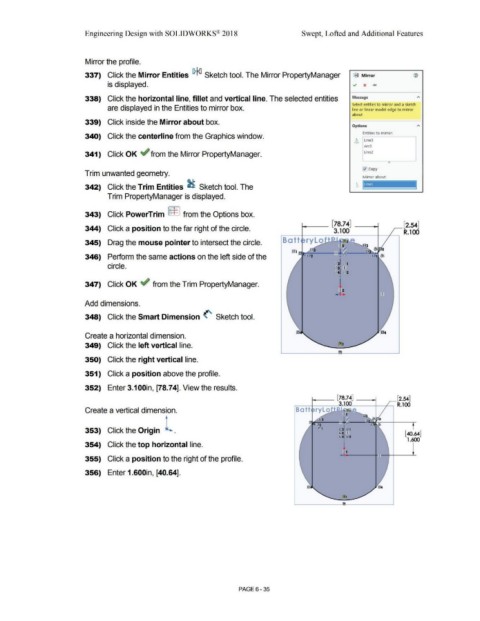
Mirror the profile.
337) Click the Mirror Entities !Pie{] Sketch tool. The Mirror PropertyManager !?I,{] Mirror ®
is displayed. ~ x .....
338) Click the horizontal line, fillet and vertical line. The selected entities Message "'
Select entities to mirror and a sketch
are displayed in the Entities to mirror box. line or linear model edge to mirror
about
339) Click inside the Mirror about box.
Options
Entities to mirror.
340) Click the centerline from the Graphics window.
L~ Line3
Arc3
341) Click OK ~ from the Mirror PropertyManager. Line2
0
j0copy
Trim unwanted geometry.
Mirror about:
--
342) Click the Trim Entities ~ Sketch tool. The h
,....
Trim PropertyManager is displayed.
343) Click PowerTrim [===F 1 from the Options box.
[78.74] [2.54]
344) Click a position to the far right of the circle. 3.100 R.100
345) Drag the mouse pointer to intersect the circle. rylo 12
-~:
346) Perform the same actions on the left side of the •
circle. ,0~ ~ .
)21~ I
%, %2
•
347) Click OK ~ from the Trim PropertyManager. 1
12
.. 4 ..
Add dimensions.
348) Click the Smart Dimension (' Sketch tool.
Create a horizontal dimension.
349) Click the left vertical line.
350) Click the right vertical line.
351) Click a position above the profile.
352) Enter 3.100in, [78.74]. View the results.
[78.74] (2.54]
R.100
Create a vertical dimension. Batt rylo
! 2
-L.~
er:sl J2l't
353) Click the Origin • JZlO' I [40.64]
12141 l2f2
• 1.600
354) Click the top horizontal line.
~2
355) Click a position to the right of the profile.
356) Enter 1.600in, [40.64].
J?J,4
PAGE 6-35