
Page 511 - Subyek Computer Aided Design - [David Planchard] Engineering Design with SOLIDWORKS
P. 511
Engineering Design with SOLIDWORKS® 2018 Swept, Lofted and Additional Features
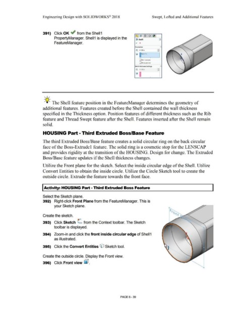
391) Click OK ~ from the Shell 1
~ ~ ~ ~ ~
PropertyManager. Shell 1 is displayed in the {! Shell1 d)
FeatureManager. ~ x
Paramete,rs A
G 0.100in I :
fj 11Face<1>
I
•
O Shell outward
O Show preview
Multi·thickness Settings A
•
G 0.100in --.
•
I
Ii ]
•
, 1 /
-;Q~ The Shell feature position in the F eatureManager determines the geometry of
additional features. Features created before the Shell contained the wall thickness
specified in the Thickness option. Position features of different thickness such as the Rib
feature and Thread Swept feature after the Shell. Features inserted after the Shell remain
solid.
HOUSING Part - Third Extruded Boss/Base Feature
The third Extruded Boss/Base feature creates a solid circular ring on the back circular
face of the Boss-Extrude 1 feature. The solid ring is a cosmetic stop for the LENSCAP
and provides rigidity at the transition of the HOUSING. Design for change. The Extruded
Boss/Base feature updates if the Shell thickness changes.
Utilize the Front plane for the sketch. Select the inside circular edge of the Shell. Utilize
Convert Entities to obtain the inside circle. Utilize the Circle Sketch tool to create the
outside circle. Extrude the feature towards the front face.
I Activity: HOUSING Part - Third Extruded Boss Feature
Select the Sketch plane.
392) Right-click Front Plane from the FeatureManager. This is
your Sketch plane.
Create the sketch.
393) Click Sketch C from the Context toolbar. The Sketch
toolbar is displayed.
394) Zoom-in and click the front inside circular edge of Shell 1
as illustrated.
395) Click the Convert Entities © Sketch tool.
Create the outside circle. Display the Front view.
396) Click Front view ~ .
PAGE 6 - 39