
Page 513 - Subyek Computer Aided Design - [David Planchard] Engineering Design with SOLIDWORKS
P. 513
Engineering Design with SOLIDWORKS® 2018 Swept, Lofted and Additional Features
In order for a model to eject from a mold, all faces
~ rm ~ $ ~ ~ I ~ 1·~ I$ : ~'J
must draft away from the parting line which divides ii?, Draft2 (1) ~ DraftXpert (1)
the core from the cavity. Cavity side faces display a .; x I ® .; x t)
positive draft and core side faces display a negative ~ ual loraftXpert] , Man-ual~,D-r~ -~p-ert!
Type of Draft "' •-A-dd-,-f c- ha- ng--,e l
draft. Design specifications include a minimum @ Neutral plane
draft angle, usually less than 5deg. O Parting line Items to Draft "'
Ostep draft ti !Bl v I :
Draft Angle "' I'-
For the model to eject successfully, all faces must II I
ti l1deg ¥.)
display a draft angle greater than the minimum Neutral Plane "' ~ II I
specified by the Draft Angle. The Draft feature, ~ II I Apoly •
Draft Analysis Tools and DraftXpert utilize the Faces to Draft "' Draft Analysis
~1
draft angle to determine what faces require J 0Auto paint
- Positive draft
additional draft base on the direction of pull. Face propagation: 1.00
[None v
, ,/
0.50
-;Q~ You can apply a draft angle as a part of an
0.00
Extruded Boss/Base or Extruded Cut feature.
Negative draft
The Draft PropertyManager provides the ability to select either the
Manual or DraftXpert tab. Each tab has a separate menu and option selections. The Draft
PropertyManager displays the appropriate selections based on the type of draft you
create.
, ,/
-;Q~ The DraftXpert PropertyManager provides the ability to manage the creation and
modification of all Neutral Plane drafts. Select the draft angle and the references to the
draft. The DraftXpert manages the rest.
I Activity: HOUSING Part - Draft Feature
Insert the Draft feature.
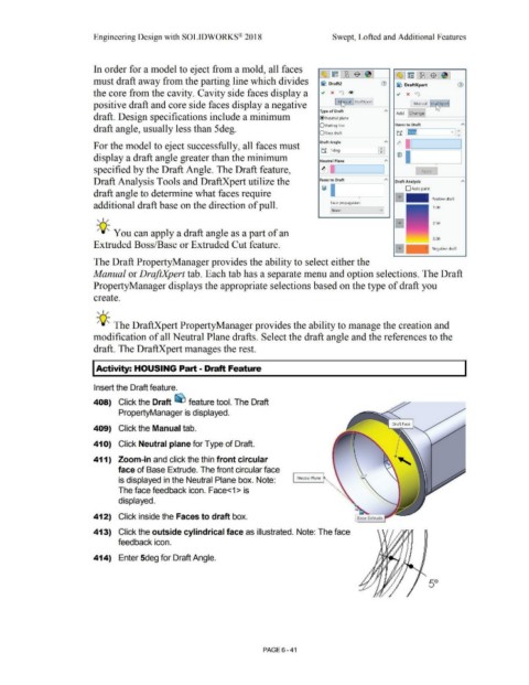
408) Click the Draft ~ feature tool. The Draft
PropertyManager is displayed.
409) Click the Manual tab.
41 O) Click Neutral plane for Type of Draft.
411) Zoom-in and click the thin front circular
face of Base Extrude. The front circular face
is displayed in the Neutral Plane box. Note: Neutral Plane
The face feedback icon. Face<1>is
displayed.
412) Click inside the Faces to draft box. Base Extrude
413) Click the outside cylindrical face as illustrated. Note: The face
feedback icon.
414) Enter 5deg for Draft Angle.
50
PAGE 6 - 41