
Page 516 - Subyek Computer Aided Design - [David Planchard] Engineering Design with SOLIDWORKS
P. 516
Swept, Lofted and Additional Features Engineering Design with SOLIDWORKS® 2018
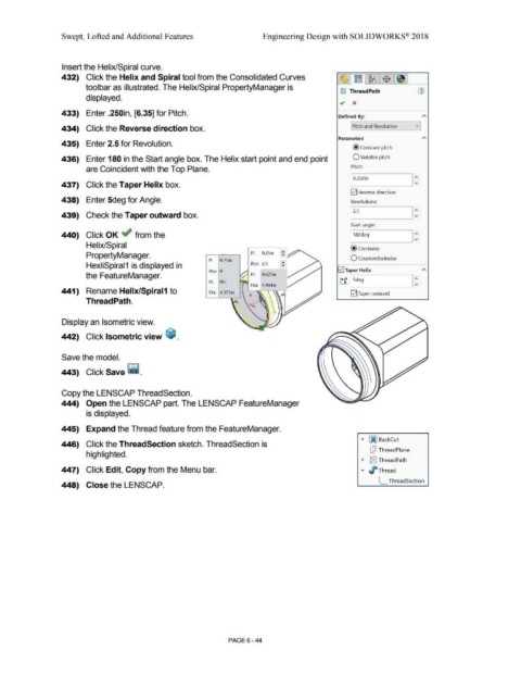
Insert the Helix/Spiral curve.
432) Click the Helix and Spiral tool from the Consolidated Curves [8]1 ~ ~ ~
~ -
toolbar as illustrated. The Helix/Spiral PropertyManager is
jg ThreadPath (1)
displayed.
.; x
433) Enter .250in, [6.35] for Pitch.
Defined By: A
vi
[Pitch and Revolution
434) Click the Reverse direction box.
Parameters A
435) Enter 2.5 for Revolution.
@constant pitch
436) Enter 180 in the Start angle box. The Helix start point and end point O Variable pitch
are Coincident with the Top Plane. Pitch:
I 0.250in I:
437) Click the Taper Helix box.
E2] Reverse direction
438) Enter 5deg for Angle. Revolutions:
439) Check the Taper outward box. 12.s I:
Start angle:
440) Click OK ~ from the I 180deg I:
Helix/Spiral @clockwise
PropertyManager. P: 0.25in ~
P: 0 '>S' 10 O Counterclockwise
,L.
HexliSpiral1 is displayed in Rev: 2.5 ~
Rev: 0 E2J Taper Helix A
the FeatureManager. './.'.:: H: 0.625in
H: Oin ~ t:f I Sdeg I:
Dia: 4.484in
441) Rename Helix/Spiral1 to Dia: 4.37Sin E2] Taper outward
Thread Path.
Display an Isometric view.
442) Click Isometric view ~ .
Save the model.
443) Click Save - ·
Copy the LENSCAP ThreadSection.
444) Open the LENSCAP part. The LENSCAP FeatureManager
is displayed.
445) Expand the Thread feature from the FeatureManager.
• ~ BackCut
446) Click the ThreadSection sketch. ThreadSection is
dJ ThreadPlane
highlighted.
• g ThreadPath
447) Click Edit, Copy from the Menu bar. ... J/ Thread
[__ ThreadSection
448) Close the LENSCAP.
PAGE 6- 44