
Page 515 - Subyek Computer Aided Design - [David Planchard] Engineering Design with SOLIDWORKS
P. 515
Engineering Design with SOLIDWORKS® 2018 Swept, Lofted and Additional Features
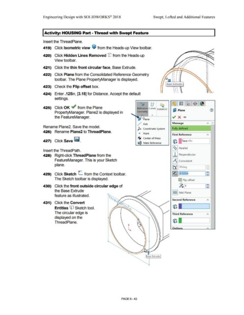
I Activity: HOUSING Part - Thread with Swept Feature
Insert the ThreadPlane.
419) Click Isometric view ~ from the Heads-up View toolbar.
,
, .
I ~ ....
•
420) Click Hidden Lines Removed tE'J from the Heads-up • ,• •
View toolbar.
421) Click the thin front circular face, Base Extrude.
. . I •
• I
. . '
422) Click Plane from the Consolidated Reference Geometry • ' . '
• I
' I ' •
I
I I
•
toolbar. The Plane PropertyManager is displayed. I I I I I I I I
I I I I
Base Extrude
423) Check the Flip offset box. •
' I I I
' I ' '
' 1 I \
. . .
• • • •
' . , '
424) Enter .125in, [3.18] for Distance. Accept the default •
settings.
g~ ') ("
' u ~
425) Click OK ~ from the Plane Reference Curves lnstant3D
uJ Plane
PropertyManager. Plane2 is displayed in Geometry
the FeatureManager.
lane
,
,./· Axis Message A A
Rename Plane2. Save the model.
).. Coordinate System Fully defined
426) Rename Plane2 to ThreadPlane.
<i Point
First Reference A
·S· Center of Mass
427) Click Save ~ . • Ii) Face<1 >
~ Mate Reference
l~I Parallel
Insert the ThreadPath.
428) Right-click ThreadPlane from the I I I Perpendicular
FeatureManager. This is your Sketch IA j Coincident
plane.
j~ j 9odeg
429) Click Sketch L.. from the Context toolbar. ,~ 11b.12Sin I : ~
The Sketch toolbar is displayed.
ij Flip offset
430) Click the front outside circular edge of ~ .__I 1 __ _____.I~
the Base Extrude
S Mid Plane
feature as illustrated.
Second Reference A
431) Click the Convert
Entities CO Sketch tool.
The circular edge is Third Reference A
displayed on the
Thread Plane.
A
Base Extrude
PAGE 6 - 43