
Page 510 - Subyek Computer Aided Design - [David Planchard] Engineering Design with SOLIDWORKS
P. 510
Swept, Lofted and Additional Features Engineering Design with SOLIDWORKS® 2018
Insert the second Extruded Boss/Base feature.
~
379) Click the Extruded Boss/Base feature tool. The Boss-Extrude ~ ~ $ ~
PropertyManager is displayed. ~ Boss-Extrude (])
v x ®
380) Enter 4.400in, [111. 76] for Depth in Direction 1.
From "'
381) Click the Draft On/Off box. !sketch Plane v .
Direction 1 "'
382) Enter 1 deg for Draft Angle. v
ll::J ~ ind
,,.
383) Click OK ~ from the Boss-Extrude PropertyManager. -- •
~ tE
14.400in
Display a Right view. E2J Merge resu It
~ [1deg 1-P
384) Click Right view @ .
O Draft outward
Rename Boss-Extrude2. Save the model.
385) Rename Boss-Extrude2 to Boss-Battery.
386) Click Save - .
HOUSING Part - Shell Feature
The Shell feature removes material_ Use the Shell feature to
remove the front face of the HOUSING. In the injection-
molded process, the body wall
thickness remains constant. souDwoRKs x
I The Thickness value is greater than the Minimum radius of Curvature. The shell may succeed,
, 1 /
• but could cause undesirable results, such as bad geometry. To find the Minimum radius of
~Q;. A dialog box is displayed if Curvature, use Tools, Check.
the thickness value is greater than
O Don't show again in this session OK Cancel
the Minimum radius of
Curvature.
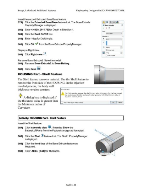
I Activity: HOUSING Part - Shell Feature
Insert the Shell feature.
387) Click Isometric view ~ . If needed Show the
BatteryloftPlane from the FeatureManager as illustrated.
388) Click the Shell (8 feature tool. The Shell1 PropertyManager
is displayed.
389) Click the front face of the Base Extrude feature as
illustrated.
390) Enter .1 OOin, [2.54] for Thickness.
PAGE 6 - 38