Page 512 - Subyek Computer Aided Design - [David Planchard] Engineering Design with SOLIDWORKS
P. 512

Swept, Lofted and Additional Features                                                                                                                      Engineering Design with SOLIDWORKS® 2018


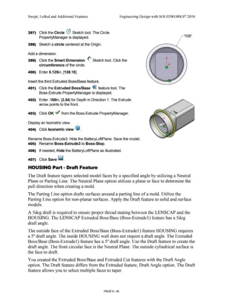
                                                397)  Click the Circle 0  Sketch tool. The Circle

                                                                                                                                                                                                                                                                                                                        [130.18nm]
                                                                   PropertyManager is displayed.                                                                                                                                                                                                                          0 5.12&1


                                                398)  Sketch a circle centered at the Origin.


                                                Add a dimension.


                                                399)  Click the Smart Dimension  <' Sketch tool. Click the


                                                                   circumference of the circle.


                                                400)  Enter 5.125in, [130.18].


                                                Insert the third Extruded Boss/Base feature.


                                                401)  Click the Extruded Boss/Base  ~ feature tool. The


                                                                   Boss-Extrude PropertyManager is displayed.


                                                402)  Enter .1 OOin, [2.54] for Depth in Direction 1. The Extrude


                                                                   arrow points to the front.


                                                403)  Click OK ~ from the Boss-Extrude PropertyManager.


                                                Display an Isometric view.


                                                404)  Click Isometric view  ~ .


                                                Rename Boss-Extrude3. Hide the BatteryloftPlane. Save the model.


                                                405)  Rename Boss-Extrude3 to Boss-Stop.


                                                406)  If needed, Hide the BatteryloftPlane as illustrated.


                                                407)  Click Save ~ .


                                                HOUSING Part- Draft Feature


                                                The Draft feature tapers selected model faces by a specified angle by utilizing a Neutral


                                                Plane or Parting Line. The Neutral Plane option utilizes a plane or face to determine the


                                                pull direction when creating a mold.


                                                The Parting Line option drafts surfaces around a parting line of a mold. Utilize the


                                                Parting Line option for non-planar surfaces. Apply the Draft feature to solid and surface


                                                models.


                                                A 5deg draft is required to ensure proper thread mating between the LENSCAP and the


                                                HOUSING. The LENSCAP Extruded Boss/Base (Boss-Extrude!) feature has a 5deg


                                                draft angle.


                                                The outside face of the Extruded Boss/Base (Boss-Extrude!) feature HOUSING requires


                                                a 5° draft angle. The inside HOUSING wall does not require a draft angle. The Extruded


                                                Boss/Base (Boss-Extrude 1) feature has a 5° draft angle. Use the Draft feature to create the


                                                draft angle. The front circular face is the Neutral Plane. The outside cylindrical surface is


                                                the face to draft.


                                                You created the Extruded Boss/Base and Extruded Cut features with the Draft Angle


                                                option. The Draft feature differs from the Extruded feature, Draft Angle option. The Draft


                                                feature allows you to select multiple faces to taper.


                                                                                                                                                                                PAGE 6 - 40
   507   508   509   510   511   512   513   514   515   516   517