
Page 509 - Subyek Computer Aided Design - [David Planchard] Engineering Design with SOLIDWORKS
P. 509
Engineering Design with SOLIDWORKS® 2018 Swept, Lofted and Additional Features
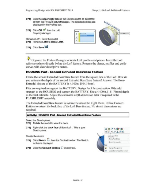
371) Click the upper right side of the SketchSquare as illustrated
or from the Fly-out FeatureManager. The selected entities are
displayed in the Profiles box.
372) Click OK ~ from the Loft
Profiles
PropertyManager. 0
<>
Rename Loft1 . Save the model.
373) Rename Loft1 to Boss-Loft1.
374) Click Save ~ -
, 1 /
-;Q~ Organize the FeatureManager to locate Loft profiles and planes. Insert the Loft
reference planes directly before the Loft feature. Rename the planes, profiles and guide
curves with clear descriptive names.
HOUSING Part- Second Extruded Boss/Base Feature
Create the second Extruded Boss/Base feature from the square face of the Loft. How do
you estimate the depth of the second Extruded Boss/Base feature? Answer: The Boss-
Extrude 1 feature of the BATTERY is 4.lOOin, [104.14mm].
Ribs are required to support the BATTERY. Design for Rib construction. Ribs add
strength to the HOUSING and support the BATTERY. Use a 4.400in, [111 .76mm] depth
as the first estimate. Adjust the estimated depth dimension later if required in the
FLASHLIGHT assembly.
The Extruded Boss/Base feature is symmetric about the Right Plane. Utilize Convert
Entities to extract the back face of the Loft Base feature. No sketch dimensions are
required.
I Activity: HOUSING Part - Second Extruded Boss/Base Feature
Select the Sketch plane.
375) Rotate the model to view the back.
376) Right-click the back face of Boss-Loft1. This is your
~ ~ !~ ., ~ · ~
Sketch plane.
~ ® fe)J. (B (!)
'
Create the sketch. I ~:k~tc'h r Tools •
Zoom/Pan/Rotate •
377) Click Sketch L from the Context toolbar. The Sketch
Recent Commands •
toolbar is displayed.
378) Click the Convert Entities © Sketch tool. O Change Transparency
c:i'il Create Plane Parallel to Screen
PAGE6 -37