
Page 520 - Subyek Computer Aided Design - [David Planchard] Engineering Design with SOLIDWORKS
P. 520
Swept, Lofted and Additional Features Engineering Design with SOLIDWORKS® 2018
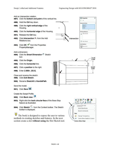
Add an Intersection relation.
487) Click the bottom end point of the vertical line. ~ Properties (1)
~ .....
488) Hold the Ctrl key down.
Selected Entities A
489) Click the right vertical edge of the Edge<l>
Edge<2>
Housing. + Pointl
0
490) Click the horizontal edge of the Housing. Exining Relations A
.h. IntersectionO
491) Release the Ctrl key.
492) Click Intersection X. from the Add Intersection
Relations box.
(D Fully Defined
Add Relations A
493) Click OK ~ from the Properties -·--·"'1
i ~, Jntersection
PropertyManager. ~
Add a dimension.
494) Click the Smart Dimension <' Sketch
tool.
,_[12.70]
R.500
495) Click the Origin.
496) Click the horizontal line. +
497) Click a position to the right. [63.50]
2.500
498) Enter 2.500in, [63.5].
Close and rename the sketch.
499) Click Exit Sketch.
500) Rename Sketch8 to HandlePath.
Save the model.
501) Click Save ~ -
Create the Swept Profile.
502) Click Back view ~ .
503) Right-click the back circular face of the Boss-Stop
feature as illustrated.
I Sketch ~n Tools •
504) Click Sketch L from the Context toolbar. The Sketch
Zoom/Pan/Rotate •
toolbar is displayed.
Recent Commands •
, ,/
Face
;Q;. The book is designed to expose the user to various '-) Change Transparency
methods in creating sketches and features. In the next C/iJ Create Plane Parallel to Screen
section create a slot without using the Slot Sketch tool. Feature {Boss-Stop)
PAGE 6- 48