
Page 524 - Subyek Computer Aided Design - [David Planchard] Engineering Design with SOLIDWORKS
P. 524
Swept, Lofted and Additional Features Engineering Design with SOLIDWORKS® 2018
Rename Sweep. Save the model.
562) Rename Sweep to Handle.
563) Click Save ~ .
How does the Handle Swept feature interact with other parts in the FLASHLIGHT
assembly? Answer: The Handle requires an Extruded Cut to insert the SWITCH.
HOUSING Part - Extruded Cut Feature with Up To Surface
Create an Extruded Cut in the Handle for the SWITCH. Utilize the top face of the Handle
for the Sketch plane. Create a circular sketch centered on the Handle.
Utilize the Up To Surface End Condition in Direction 1. Select the inside surface of the
HOUSING for the reference surface.
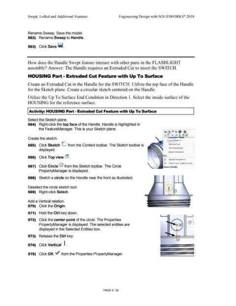
I Activity: HOUSING Part - Extruded Cut feature with Up To Surface
Select the Sketch plane.
564) Right-click the top face of the Handle. Handle is highlighted in
the FeatureManager. This is your Sketch plane.
~~ ! Q +t ~·~
c:a1 ~ fo J. !B (]
Create the sketch.
I Sketch f angency
565) Click Sketch L from the Context toolbar. The Sketch toolbar is Selection Tools
Zoom/Pan/Rotate
displayed.
Recent Commands
Face
566) Click Top view @ .
~ Change Transparency
r.i> Create Plane Parallel to Screen
567) Click Circle 0 from the Sketch toolbar. The Circle Feature (Handle)
PropertyManager is displayed.
568) Sketch a circle on the Handle near the front as illustrated.
Deselect the circle sketch tool.
569) Right-click Select.
Add a Vertical relation.
570) Click the Origin.
571) Hold the Ctrl key down.
572) Click the center point of the circle. The Properties ...
PropertyManager is displayed. The selected entities are rBJ I
displayed in the Selected Entities box.
573) Release the Ctrl key.
574) Click Vertical I .
575) Click OK ~ from the Properties PropertyManager.
PAGE6-52