
Page 525 - Subyek Computer Aided Design - [David Planchard] Engineering Design with SOLIDWORKS
P. 525
Engineering Design with SOLIDWORKS® 2018 Swept, Lofted and Additional Features
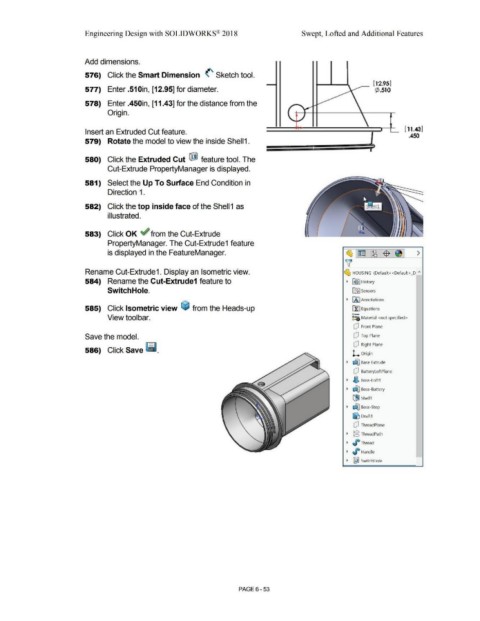
Add dimensions.
576) Click the Smart Dimension <'- Sketch tool.
[12.95)
577) Enter .510in, [12.95] for diameter. \ ¢ .510
578) Enter .450in, [11.43] for the distance from the ,
r "'I.,-
Origin.
\.. ~ \
,
- I ( 11.43)
'
Insert an Extruded Cut feature. -
.450
579) Rotate the model to view the inside Shell1.
- - - --
-
I
580) Click the Extruded Cut ij) feature tool. The
Cut-Extrude PropertyManager is displayed.
581) Select the Up To Surface End Condition in
Direction 1 .
582) Click the top inside face of the Shell 1 as
illustrated.
583) Click OK ~ from the Cut-Extrude
PropertyManager. The Cut-Extrude1 feature
is displayed in the FeatureManager. ~ ~ ~ -$- ~ >
'v
Rename Cut-Extrude1. Display an Isometric view. ~ HOUSING (Default< <Default> _D "
584) Rename the Cut-Extrude1 feature to • R9 I History
Switch Hole. ifi:J Sensors
• (A I Annotations
585) Click Isometric view ~ from the Heads-up ri:] Equations
o-
View toolbar. ~:e Material <not specified>
dJ Front Plane
Save the model. Q Top Plane
dJ Right Plane
586) Click Save ~ -
L Origin
• dJ'.J Base Extrude
dJ BatteryloftPlane
• ~ Boss-Loft1
• dJ'.J Boss-Battery
[!iJ Shell1
• ~ Boss-Stop
~ Draft1
dJ ThreadPlane
• @ ThreadPath
• J° Thread
• ~ Handle
• ~ SwitchHole
PAGE 6 - 53