Page 526 - Subyek Computer Aided Design - [David Planchard] Engineering Design with SOLIDWORKS
P. 526

Swept, Lofted and Additional Features                                                                                                                      Engineering Design with SOLIDWORKS® 2018


                                                HOUSING Part - First Rib and Linear Pattern Feature


                                                The Rib ,  feature adds material between contours of existing geometry. Use Ribs to add


                                                structural integrity to a part.


                                                A Rib requires:


                                                •  A sketch


                                                •  Thickness


                                                •  Extrusion direction


                                                The first Rib profile is sketched on the Top Plane. A 1 ° draft angle is required for


                                                manufacturing. Determine the Rib thickness by the manufacturing process and the


                                                material.


                                                   , 1 /


                                                  ;Q;.  Rule of thumb states that the Rib thickness is Yz the part wall thickness. The Rib


                                                thickness dimension is .100 inches, [2.54mm] for illustration purposes.


                                                The HOUSING requires multiple Ribs to support the BATTERY. A Linear Pattern


                                                feature creates multiple instances of a feature along a straight line. Create the Linear


                                                Pattern feature in two directions along the same vertical edge of the HOUSING.


                                                   , 1 /


                                                  ;Q;.  The Instance to Vary option in the Linear Pattern PropertyManager allows you to


                                                vary the dimensions and locations of instances in a feature pattern after it is created. You


                                                can vary the dimensions of a series of instances, so that each instance is larger or smaller


                                                than the previous one. You can also change the dimensions of a single instance in a


                                                pattern and change the position of that instance relative to the seed feature of the pattern.


                                                For linear patterns, you can change the spacing between the columns and rows in the


                                                pattern.


                                                  Activity: HOUSING Part - First Rib and Linear Pattern Feature


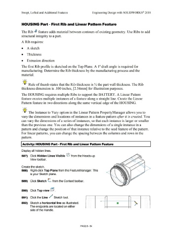
                                                Display all hidden lines.


                                                587)  Click Hidden Lines Visible ® from the Heads-up


                                                                   View toolbar.


                                                Create the sketch.


                                                588)  Right-click Top Plane from the FeatureManager. This


                                                                   is your Sketch plane.


                                                589)  Click Sketch  (_ from the Context toolbar.


                                                590)  Click Top view @.


                                                591)  Click the Line  /                                                Sketch tool.


                                                592)  Sketch a horizontal line as illustrated.


                                                                   The endpoints are located on either


                                                                   side of the Handle.


                                                                                                                                                                                PAGE6 - 54
   521   522   523   524   525   526   527   528   529   530   531