
Page 523 - Subyek Computer Aided Design - [David Planchard] Engineering Design with SOLIDWORKS
P. 523
Engineering Design with SOLIDWORKS® 2018 Swept, Lofted and Additional Features
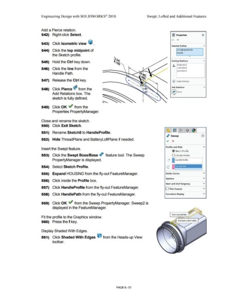
Add a Pierce relation.
542) Right-click Select. ~ Properties ®
.., .....
543) Click Isometric view ~ .
Selected Entities "'
544) Click the top midpoint of Line2@HandlePath
Point15
the Sketch profile.
0
545) Hold the Ctrl key down. Existing Relations "'
.h MidpointU
546) Click the line from the Coincident2
Symmetricl
Handle Path.
547) Release the Ctrl key. (D Under Defined
Add Relations "'
548) Click Pierce cf; from the
[t] Pierce
Add Relations box. The
sketch is fully defined.
549) Click OK ~ from the
Properties PropertyManager.
Close and rename the sketch.
550) Click Exit Sketch.
~ I ~ [ ~ WWW I $ I
551) Rename Sketch8 to HandleProfile.
./' Sweep
552) Hide ThreadPlane and BatteryloftPlane if needed. .; x
Profile and Path
Insert the Swept feature.
@sketch Profile
553) Click the Swept Boss/Base it feature tool. The Sweep O Circular Profile
PropertyManager is displayed. O I IHandleProfile
554) Select Sketch Profile.
555) Expand HOUSING from the fly-out FeatureManager. Guide Curves v
Options v
556) Click inside the Profile box.
Start and End Tangency v
557) Click HandleProfile from the fly-out FeatureManager.
D Thin Feature v
558) Click HandlePath from the fly-out FeatureManager. Curvature Display v
559) Click OK ~ from the Sweep PropertyManager. Sweep2 is
displayed in the FeatureManager.
Path(HandlePath)
Fit the profile to the Graphics window.
560) Press the f key.
Display Shaded With Edges.
561) Click Shaded With Edges ijJ from the Heads-up View
tool bar.
PAGE 6 - 51