
Page 527 - Subyek Computer Aided Design - [David Planchard] Engineering Design with SOLIDWORKS
P. 527
Engineering Design with SOLIDWORKS® 2018 Swept, Lofted and Additional Features
Add a dimension.
-
593) Click the Smart Dimension (' ' '\
~ -- . . . ...•....•.........•.........•....••.. . .. . .....
Sketch tool.
594) Click the inner back edge.
[ 4.45]
.175
595) Click the horizontal line.
596) Click a position to the right off the
profile. ~ ~ [p3 ~
597) Enter .175in, [4.45]. ___ ___ _i ____ ~_ ~ .... 4J Rib1
v x ®
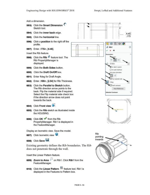
Insert the Rib feature.
Parameters
598) Click the Rib , feature tool. The
-
Rib PropertyManager is - -
- ~ -
displayed. •
•
599) Click the Both Sides button. • At sketch plane
O At wall interface
600) Click the Draft On/Off box. Extrusion direction:
601) Enter 1 deg for Draft Angle.
602) Enter .100in, [2.54] for Rib Thickness.
603) Click the Parallel to Sketch button.
The Rib direction arrow points to the [ Next Reference
back. Flip the material side if required.
Selected Contours v
Select the Flip material side check box
if the direction arrow does not point
towards the back.
604) Click Front view ~ .
605) Click the Rib sketch as illustrated inside
the HOUSING.
606) Click OK ~ from the Rib
PropertyManager. Rib1 is displayed in
the FeatureManager.
Display an Isometric view. Save the model.
Rib
607) Click Isometric view ~ .
pointing
inwards
608) Click Save ~ .
Existing geometry defines the Rib boundaries. The Rib
does not penetrate through the wall.
Insert the Linear Pattern feature.
609) Zoom to Area JY. on Rib1. Click Rib1 from the
FeatureManager.
[>()
610) Click the Linear Pattern eiei feature tool. Rib1 is
displayed in the Features to Pattern box.
PAGE 6-55