
Page 485 - Subyek Computer Aided Design - [David Planchard] Engineering Design with SOLIDWORKS
P. 485
Engineering Design with SOLIDWORKS® 2018 Swept, Lofted and Additional Features
I Activity: Switch Part - • oft Base Feature
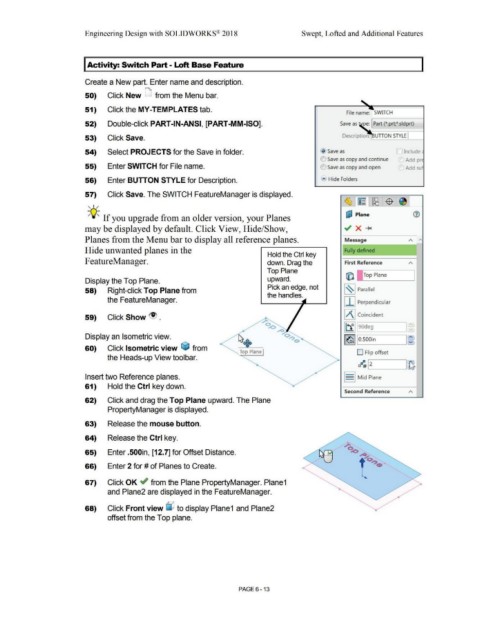
Create a New part. Enter name and description.
50) Click New D from the Menu bar.
51) Click the MY-TEMPLATES tab.
File name: SWITCH
52) Double-click PART-IN-ANSI, [PART-MM-ISO]. Save as pe: Part (*.prt;*.sldprt)
53) Click Save. Description: UTION STYLE J
54) Select PROJECTS for the Save in folder. @ Save as ::J Include
C) Save as copy and continue Add pr
55) Enter SWITCH for File name. O Save as copy and open Add suf
56) Enter BUTTON STYLE for Description. .... Hide Folders
57) Click Save. The SWITCH FeatureManager is displayed.
, ,/
-;Q~ If you upgrade from an older version, your Planes uJ Plane
may be displayed by default. Click View, Hide/Show,
Planes from the Menu bar to display all reference planes. Message A I'\
Hide unwanted planes in the Fully defined
Hold the Ctrl key
F eatureManager. down. Drag the First Reference
Top Plane
(Q I !Top Plane
Display the Top Plane. upward.
Pick an edge, not
58) Right-click Top Plane from ,~ , Parallel
the handles.
the FeatureManager. j I j Perpendicular
59) Click Show ~ . IAI Coincident
lt1] 90deg J .::.J
-- J
Display an Isometric view.
I (o!j I O.SOOin I:~
60) Click Isometric view ~ from
Top Plane D Flip offset
the Heads-up View toolbar.
~ .__I 2 _ _____.I~
Insert two Reference planes. S Mid Plane
61) Hold the Ctrl key down.
Second Reference
62) Click and drag the Top Plane upward. The Plane
PropertyManager is displayed.
63) Release the mouse button.
64) Release the Ctrl key.
65) Enter .500in, [12.7] for Offset Distance.
66) Enter 2 for# of Planes to Create.
67) Click OK ~ from the Plane PropertyManager. Plane1
and Plane2 are displayed in the FeatureManager.
68) Click Front view L)J to display Plane1 and Plane2
offset from the Top plane.
PAGE 6 - 13