
Page 40 - Enhancing CAD Drawings with Photoshop
P. 40
4386.book Page 23 Monday, November 15, 2004 3:27 PM
USING LAYERS 23
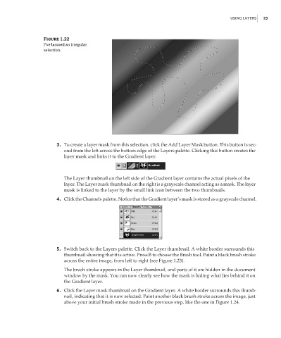
Figure 1.22
I’ve lassoed an irregular
selection.
3. To create a layer mask from this selection, click the Add Layer Mask button. This button is sec-
ond from the left across the bottom edge of the Layers palette. Clicking this button creates the
layer mask and links it to the Gradient layer.
The Layer thumbnail on the left side of the Gradient layer contains the actual pixels of the
layer. The Layer mask thumbnail on the right is a grayscale channel acting as a mask. The layer
mask is linked to the layer by the small link icon between the two thumbnails.
4. Click the Channels palette. Notice that the Gradient layer’s mask is stored as a grayscale channel.
5. Switch back to the Layers palette. Click the Layer thumbnail. A white border surrounds this
thumbnail showing that it is active. Press B to choose the Brush tool. Paint a black brush stroke
across the entire image, from left to right (see Figure 1.23).
The brush stroke appears in the Layer thumbnail, and parts of it are hidden in the document
window by the mask. You can now clearly see how the mask is hiding what lies behind it on
the Gradient layer.
6. Click the Layer mask thumbnail on the Gradient layer. A white border surrounds this thumb-
nail, indicating that it is now selected. Paint another black brush stroke across the image, just
above your initial brush stroke made in the previous step, like the one in Figure 1.24.