Page 129 - Fluid Mechanics and Thermodynamics of Turbomachinery
P. 129

110 Fluid Mechanics, Thermodynamics of Turbomachinery

                                        3.0
                                                h tt  =  0.82  0.84  0.86
                                      Stage loading coefficient, y =  DW/U 2  2.0  e  =  140°  120°  100° 0.92  0.90  0.86
                                                            0.88


                                                 R
                                                          80°
                                        1.0
                                                             60°
                                                                               0.82


                                         0                         40°         0.84
                                                       0.5          1.0          1.5
                                                      Flow coefficient, f = c /U
                                                                     x
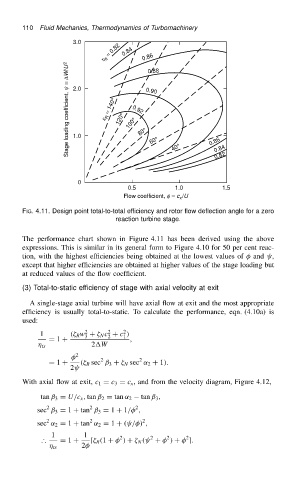
                          FIG. 4.11. Design point total-to-total efficiency and rotor flow deflection angle for a zero
                                                    reaction turbine stage.

                          The performance chart shown in Figure 4.11 has been derived using the above
                          expressions. This is similar in its general form to Figure 4.10 for 50 per cent reac-
                          tion, with the highest efficiencies being obtained at the lowest values of   and  ,
                          except that higher efficiencies are obtained at higher values of the stage loading but
                          at reduced values of the flow coefficient.

                          (3) Total-to-static efficiency of stage with axial velocity at exit
                            A single-stage axial turbine will have axial flow at exit and the most appropriate
                          efficiency is usually total-to-static. To calculate the performance, eqn. (4.10a) is
                          used:
                                                 2
                                                      2
                                           2
                               1       .  R w C   N c C c /
                                           3
                                                      1
                                                 2
                                 D 1 C                 ,
                                ts           2W
                                         2     2          2
                                 D 1 C    .  R sec ˇ 3 C   N sec ˛ 2 C 1/.
                                       2
                          With axial flow at exit, c 1 D c 3 D c x , and from the velocity diagram, Figure 4.12,
                                                           tan ˇ 3 ,
                               tan ˇ 3 D U/c x , tan ˇ 2 D tan ˛ 2
                                 2
                                                         2
                                            2
                              sec ˇ 3 D 1 C tan ˇ 3 D 1 C 1/  ,
                                 2          2              2
                              sec ˛ 2 D 1 C tan ˛ 2 D 1 C . / / ,
                                  1        1
                               ∴    D 1 C    [  R .1 C   / C   N .  C   / C   ].
                                                                       2
                                                                  2
                                                     2
                                                             2
                                   ts     2
   124   125   126   127   128   129   130   131   132   133   134