Page 430 - T. Anderson-Fracture Mechanics - Fundamentals and Applns.-CRC (2005)
P. 430
1656_C009.fm Page 410 Monday, May 23, 2005 3:58 PM
410 Fracture Mechanics: Fundamentals and Applications
9.4 FAILURE ASSESSMENT DIAGRAMS
The Failure Assessment Diagrams (FAD) is probably the most widely used methodology for elastic-
plastic fracture mechanics analysis of structural components. The original FAD was derived from
the strip-yield plastic zone correction, as described in Section 9.4.1. The strip-yield model has
limitations, however. For example, it does not account for strain hardening. A more accurate FAD
can be derived from an elastic-plastic J-integral solution (Section 9.4.2). In addition, there are
simplified versions of the FAD that account for strain hardening but do not require a rigorous J
integral solution (Section 9.4.3).
The FAD approach is easy to implement. A highly nonlinear problem (elastic-plastic fracture)
is solved in terms of two parameters that vary linearly with applied load.
The FAD approach is also very versatile. It spans a wide range of material behavior, from
brittle fracture under linear elastic conditions to ductile overload in the fully plastic regime. The
FAD method is appropriate for welded components because it can account for residual stresses
(Section 9.4.5). The FAD can also be used for ductile tearing analysis (Section 9.4.7).
9.4.1 ORIGINAL CONCEPT
Dowling and Townley [30] and Harrison et al. [31] introduced the concept of a two-criterion FAD
to describe the interaction between brittle fracture and fully ductile rupture. The first FAD was
derived from a modified version of the strip-yield model, as described next.
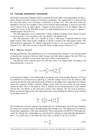
The effective stress intensity factor for a through crack in an infinite plate, according to the
strip-yield model, is given by
πσ 12 /
K eff = σ YS π a 8 lnsec (9.53)
2
π 2 σ YS
As discussed in Chapter 2, this relationship is asymptotic to the yield strength. Equation (9.53) can
be modified for real structures by replacing s with the collapse stress s for the structure. This
YS
c
would ensure that the strip-yield model predicts failure as the applied stress approaches the collapse
stress. For a structure loaded in tension, collapse occurs when the stress on the net cross-section
reaches the flow stress of the material. Thus s depends on the tensile properties of the material
c
and the flaw size relative to the total cross section of the structure. The next step in deriving a
failure assessment diagram from the strip-yield model entails dividing the effective stress intensity
by the linear elastic K:
K eff σ c 8 πσ 12 /
K I = σπ 2 lnsec 2 σ c (9.54)
This modification not only expresses the driving force in a dimensionless form but also eliminates
the square root term that contains the half-length of the through crack. Thus Equation (9.54) removes
5
the geometry dependence of the strip-yield model. This is analogous to the PD 6493:1980 approach,
where the driving force relationship was generalized by defining an equivalent through thickness
flaw . As a final step, we can define the stress ratio S and the K ratio K as follows:a r r
K
K = K eff I (9.55)
r
5 This generalization of the strip-yield model is not rigorously correct for all configurations, but it is a good approximation.

