
Page 146 - Fundamentals of Water Treatment Unit Processes : Physical, Chemical, and Biological
P. 146
Sedimentation 101
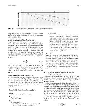
L
v H Path of organics
D v =v o Path of discrete particle
s
FIGURE 6.7 Overflow velocity as related to particle trajectory for discrete particles.
except that v o may be associated with a ‘‘design’’-settling b. Spreadsheet
velocity of particles, while SOR is more often associated Set up a spreadsheet that applies the foregoing prin-
with a regulatory limit. ciples, e.g., Equations 6.11 and 6.12. (1) Assume a
3
flow, e.g., Q ¼ 0.05 m =s (1.14 mgd) for a very small
6.3.1.3 Significance of Overflow Velocity plant serving a population of about 10,000; (2)
obtain a value for v o for clay particles from Table
Camp’s idea of overflow velocity was a fundamental innov-
6.9; (3) calculate the quantity (wL); (4) assume sev-
ation, in that basin depth, D, was deleted from the design
eral trial-and-error values for v H , e.g., 0.30 m=s,
relationship and, at the same time, detention time was shown such that scour is not likely; (5) calculate the corre-
to have no bearing on removal. In other words, overflow sponding value for (wD); (6) assume values for D
velocity, v o , is the basis for sizing a basin. Thus, a settling and calculate, w, i.e., w ¼ (wD)=D; and (7) finally,
basin can be as shallow as desired. The caveat is that the calculate, L, i.e., L ¼ (wL)=w.
horizontal velocity, v H , should not cause scour, i.e., resuspen-
sion of settled particles, that is unacceptable. With such limit Discussion
defined for v H , the product, wD, is determined, i.e., by Equa- Table Ex6.2 illustrates how to determine the basin dimen-
tion 6.12: sions, D, w, and L with a few trials based upon the idea of
a selected overflow velocity, v o , and a limit for horizontal
Q velocity, v H . As noted, all the particles with settling vel-
(6:12)
v H ¼ ocity, v s , that are less than the overflow velocity, v o ,
wD
i.e., v s < v o , will be removed. The table could be set up
by assuming w=L as an alternative to assuming D (or, for
The ratios w=D and w=L are based upon empirical
that matter, w or L). A spreadsheet provides a more con-
guidelines and practical considerations. For example, if v o
venient means for doing such calculations.
is given as a criterion, then by Equation 6.11, wL is fixed,
and if w=L is given by guidelines, L may be calculated (and
then D). 6.3.1.5 Partial Removals for Particles with Fall
6.3.1.4 Insignificance of Detention Time Velocities, v s < v o
Any suspension has a distribution of particle sizes, some with
As a note, the relationship between detention time and depth
v s < v o , and some with v s > v o . All particles having v s v o ,
is as follows: u ¼ V=Q ¼ A D=Q ¼ D=v o ; therefore, v o ¼ D=u.
will be removed completely. Particles having v s < v o will be
Thus, if v o is ‘‘set’’ (based on particle-size-to-be-removed or
removed partially.
an empirical guideline), any change in u requires a propor-
To determine the partial removal of particles with v s < v o ,
tionate change in D. Example 6.2 illustrates how to apply the
consider the fraction of particles having a specific fall velocity v 1 ,
foregoing principles.
where v 1 < v o . Figure 6.8 shows the resultant velocity vector,
~ v 1 þ~ v H , for particles of this size. Letting this vector intercept
Example 6.2 Dimensions of an Ideal Basin the bottom of the basin at its far right, and then extrapolating
the vector back to the entrance of the basin shows that it
Given intercepts the vertical plane on the left side at depth d 1 .
An ideal settling basin that removes clay. Thus, all particles with fall velocity v 1 that enter the basin at
Required d d 1 will be removed. Therefore, the proportion of particles,
That size of the basin. r 1 , of fall velocity, v 1 that will be removed must be (Camp,
1946)
Solution
a. Fall velocity, v o .
Table 6.9 gives fall velocities for various particles. d 1
DP 1 (6:13)
2
For clay, v o ¼ 0.12 m=min (3.0 gpm=ft ). D
r 1 ¼