
Page 388 - Fundamentals of Water Treatment Unit Processes : Physical, Chemical, and Biological
P. 388
Rapid Filtration 343
100
Horsetooth reservoir water: influent turbidity—6.8 NTU 0.30
Conventional filtration (effluent turbidity—6.8 NTU)
90 2
HLR = 22.7 m/min (6.0 gpm/ft )
Q = 37.8 L/min (10.0 gpm)-check 0.25
80 Alum dosage as Al (SO ) 14.3H O=23.6 mg/L 0.20
•
2
4 3
2
Effluent particle counts (#/mL) 60 Chemical conditioning Breakthrough 0.15
70
50
40
30
20 Steady state 0.10
0.05
10
0 0.0
0 5 10 15 20 25
Time (h)
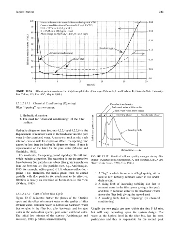
FIGURE 12.16 Effluent particle counts and turbidity from pilot filter. (Courtesy of Marinelli, F. and Carlson, K., Colorado State University,
Fort Collins, CO, Run A3C, May 6, 1999.)
12.3.2.11.1 Chemical Conditioning (Ripening) Clean back-wash water
Filter ‘‘ripening’’ has two causes: Back-wash water within media
Back-wash water above media
1. Hydraulic dispersion Ripening phase Steady-state phase
2. The need for ‘‘chemical conditioning’’ of the filter
medium
Hydraulic dispersion (see Sections 4.2.2.4 and 4.2.2.6) is the Turbidity or particles Receding limb
displacement of remnant water in the headwater and the pore
water by the coagulated water. A tracer test, such as with a salt Rising limb
solution, can evaluate the dispersion effect. The ripening time
cannot be less than the hydraulic dispersion time; 15 min is Lag
representative of the latter for the pore water (Mosher and
Elapsed time
Hendricks, 1986).
For most cases, the ripening period is perhaps 30–120 min.
FIGURE 12.17 Detail of effluent quality changes during filter
which includes dispersion. The reasoning is that the attractive startup. (Adapted from Amirtharajah, A. and Wetstein, D.P., J. Am.
force between floc particles and a bare filter grain is much less Water Works Assoc., 72(9), 519, 1980.)
than that between two floc particles (see, e.g., Amirtharajah,
1985, for example, a(floc-grain) 1.0, whereas a(floc-floc
grain) ! 1.0. Therefore, the media grains must be coated 1. A ‘‘lag’’ in which the water is of high quality, attrib-
partially with floc particles for attachment to be effective; uted to low turbidity remnant water in the under-
filtration is merely an extension of flocculation in this view drain system
(O’Melia, 1985). 2. A rising limb of increasing turbidity due first to
remnant water in the filter pores giving a first peak
and then to remnant water in the headwater (water
12.3.2.11.2 Start of Filter Run Cycle above the filter bed) giving the second peak
Figure 12.17 delineates further the phases of the filtration 3. A receding limb, that is, ‘‘ripening’’ (or chemical
cycle and the effect of remnant water on the quality of filter conditioning)
effluent water. Remnant water is defined as backwash water
that remains in the filter box after backwash and includes Usually the two peaks are seen within the first 5–15 min,
water in the under-drain system, pore water, and head water. but will vary depending upon the system design. The
The initial few minutes of the start-up (Amirtharajah and water at the highest level in the filter box has the most
Wetstein, 1980, p. 518) is characterized by particulates and thus is responsible for the second peak