
Page 533 - Fundamentals of Water Treatment Unit Processes : Physical, Chemical, and Biological
P. 533
488 Fundamentals of Water Treatment Unit Processes: Physical, Chemical, and Biological
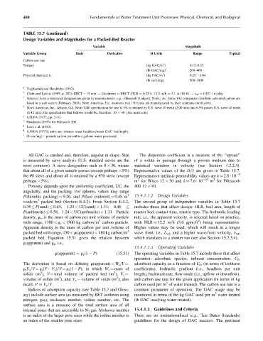
TABLE 15.7 (continued)
Design Variables and Magnitudes for a Packed-Bed Reactor
Variable Magnitude
Variable Group Basic Derivative SI Units Range Typical
Carbon use rate
3
Tertiary (kg GAC=m ) 0.12–0.23
(lb GAC=mg) i 200–400
3
Physical chemical tr. (kg PAC=m ) 0.29 ¼ 1.04
(lb carb=mg) 500–1800
a
Vagliasindi and Hendricks (1992).
b
Clark and Lykins (1989, p. 282); EBCT ¼ 15 min ! L(column) EBCT HLR 0.25 h 12.2 m=h 3.1 m (10 ft) ! v wf 0.0211 m=day.
c
Selected from commercial designations given by manufacturers; e.g., Filtrasorb (Calgon); Norit,; etc. Some 142 companies distribute activated carbon are
listed in a web search (February 2003). Norit Americas, Inc. mentions that 150 types are manufactured by their company (norit.com).
d
Norit Americas, Inc., Atlanta, GA, Norit 1240 specification for size is 5% is retained by U.S. sieve 10 mesh (2.00 mm) and 0.5% passes U.S. sieve 40 mesh
(0.42 mm); the specification that follows would be, therefore, 10 40. [See norit.com]
e
USEPA (1973, pp. 2–5).
f
Hendricks (1973) for Filtrasorb 200.
g
Love e al. (1983).
h
USEPA (1973); units are: (meters water headloss=meter GAC bed depth).
i
(lb car=mg) ¼ pounds carbon per million gallons water processed.
All GAC is crushed and, therefore, angular in shape. Size The dispersion coefficient is a measure of the ‘‘spread’’
is measured by sieve analysis (U.S. standard sieves are the of a solute in passage through a porous medium due to
most common). A sieve designation such as 8 30, means statistical variation in velocity (see Section 4.2.2.4).
that about all of a given sample passes (except perhaps <5%) Representative values of the D=v are given in Table 15.7.
the #8 sieve and about all is retained by a #30 sieve (except Representative intrinsic permeability values are k 2.8 10 9
2
2
perhaps <5%). m for Witco 12 30 and k 7.6 10 10 m for Filtrasorb
Porosity depends upon the uniformity coefficient, UC, the 400 12 40.
angularity, and the packing. For spheres, values may range
3
P(rhombic packing) ¼ 0.26, and P(face centered) ¼ 0.48 m 15.4.1.1.2 Design Variables
3
voids=m packed bed (Section E.4.2). From Section E.4.2, The second group of independent variables in Table 15.7
0.35 P(sand) 0.45, 1.23 < UC(sand) < 1.31; 0.46 includes those that affect design: HLR, bed area, length of
P(anthracite) 0.58, 1.24 < UC(anthracite) < 1.33. Particle reactor bed, contact time, reactor type. The hydraulic loading
density, r s , is the mass of carbon per unit volume of particle rate, i.e., the apparent velocity, is selected based on practice,
2
3
with range, 1300 < r s < 1500 kg carbon=m carbon particle. with HLR 12.2 m=h (5.0 gpm=ft ) being representative.
Apparent density is the mass of carbon per unit volume of Higher values may be used, which will result in a longer
packed bed with range, 430 < r(apparent) < 480 kg carbon=m 3 wave front, i.e., L wf , and a higher wave-front velocity, v wf ,
packed bed. Equation 15.51 gives the relation between which translates to a shorter run (see also Section 15.2.3.4).
r(apparent) and r s , i.e.,
15.4.1.1.3 Operating Variables
r(apparent) ¼ r (1 P) (15:51) The operating variables in Table 15.7 include those that affect
s
operation: adsorbate species, influent concentration, C 0 ,
adsorbent capacity as a function of C 0 , (in terms of isotherm
The derivation is based on defining r(apparent) ¼ W s =V ¼
r s V s =V ¼ r s (V V v )=V ¼ r s (1 P), in which W s ¼ mass of coefficients), hydraulic gradient (i.e., headloss per unit
3 3
length), backwash rate, flow mode (i.e., upflow or downflow),
solids (m ), V ¼ total volume of packed bed (m ), V s ¼
3
3
volume of solids (m ), and V v ¼ volume of voids (m ); also and carbon use rate for the given application (in terms of kg
3
recall, P V v =V. carbon used per m of water treated). The carbon use rate is a
Indices of adsorption capacity (see Table 15.7 and Gloss- common parameter of operation. The GAC usage may be
3
ary) include surface area (as measured by BET isotherm using monitored in terms of the kg GAC used per m water treated
nitrogen gas), molasses number, iodine number, etc. The (lb GAC used=mg water treated).
surface area is a measure of the total surface area of all
internal pores that are accessible to N 2 gas. Molasses number 15.4.1.2 Guidelines and Criteria
is an index of the larger pore sizes while the iodine number is There are no institutionalized (e.g., Ten States Standards)
an index of the smaller pore sizes. guidelines for the design of GAC reactors. The pertinent