
Page 157 - Gas Purification 5E
P. 157
Alkanolamines for Hydrogen Sulfine and Carbon Dioxide Removal 145
~~
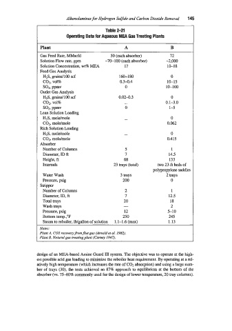
Table 2-21
Operating Data for Aqueous MEA Gas Treating Plants
Plant A
Gas Feed Rate, MMscfd 50 (each absorber) 72
Solution Flow rate. gpm -70-100 (each absorber) -2,000
Solution Concentration, wt8 MEA 17 10-18
Feed Gas Analysis
H2S, grainsllO0 scf 160-180 0
coz, vol% 0.3-0.4 10-15
Sol, ppmv 0 10-100
Outlet Gas Analysis
H2S, ,pindl00 scf 0.02-0.3 0
co2, vol% - 0.1-3.0
SOP, ppmv 0 1-5
Lean Solution Loading
H2S, moldmole 0
C02, mole/mole 0.062
Rich Solution Loading
H2S, moldmole 0
C02, moldmole 0.415
Absorber
Number of Columns 5 1
Diameter, ID ft 7 14.5
Height, ft 68 133
Internals 23 trays (total) two 23-ft beds of
polypropylene saddles
Water Wash 3 trays 2 trays
Pressure, psig 200 0
Stripper
Number of Columns 2 1
Diameter, ID, ft 7 12.5
Total trays 20 18
Wash trays - 2
Pressure, psig 12 5-10
Bottom temp.,"F 250 245
Steam to reboiler, lb/g.allon of solution 1.1-1.6 (max) 1.13
Notes:
Plant A. C02 recoveryfiom flue gas (Arnold et al. 1982).
Plcnt B, iVaturalgas treatingplant (Came 1947).
design of an MEA-based Amine Guard 111 system. The objective was to operate at the high-
est possible acid gas loading to minimize the reboiler heat requirement. By operating at a rel-
atively high temperature (which increases the rate of C02 absorption) and using a large num-
ber of trays (30), the tests achieved an 87% approach to equilibrium at the bottom of the
absorber (vs. 7540% commonly used for the design of lower temperature, 20 tray columns).