
Page 427 - Handbook of Materials Failure Analysis
P. 427
5 Deformation of Multi-Layer Coatings 425
In metal-ceramic multi-layer coatings, cracks are initiated at interfaces and
developed in hard and brittle ceramic layers and block at next interface
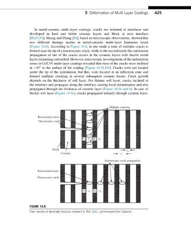
[80,83,84]. Huang and Zhang [80], based on microscopic observations, showed that
two different damage modes in metal-ceramic multi-layer laminates occur
(Figure 16.8). According to Figure 16.8, in one mode a zone of multiple cracks is
formed near the tip of a macroscopic crack, while in the second mode the continuous
propagation of one of the cracks occurs in the ceramic layers with ductile metal
layers remaining untouched. However, microscopic investigations of the indentation
zones in Cr/CrN multi-layer coatings revealed that most of the cracks were inclined
at 45° to the surface of the coating (Figure 16.9)[84]. Cracks were not located
under the tip of the indentation, but they were located at an inflection zone and
formed multiple cracking in several subsequent ceramic layers. Crack growth
depends on the thickness of soft layer. For thinner soft layer, cracks inclined at
the interface and propagate along the interface causing local delamination and also
propagated through the thickness of ceramic layer (Figure 16.9a and b). In case of
thicker soft layer (Figure 16.9c), cracks propagated initially through ceramic layer.
Multiple cracking
Renucleated crack
Macroscopic crack
m 1 c 1 m 2 c 2
Metal t m
Ceramic t c
Macroscopic crack propagation
Renucleated crack
Macroscopic crack
m 1 c 1 m 2 c 2
FIGURE 16.8
Two modes of laminate fracture showed in Ref. [80], permission from Elsevier.