
Page 418 - Industrial Wastewater Treatment, Recycling and Reuse
P. 418
390 Industrial Wastewater Treatment, Recycling, and Reuse
water for more than a week with continuous aeration to maintain DO
1–2 mg/L. Before startup, the membrane module was tested with clean
water, and its permeability was determined. After achieving MLSS of more
than 4000 mg/L, sludge filtration was started through the module. The flow
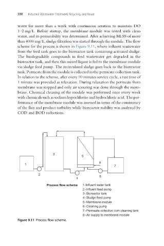
scheme for the process is shown in Figure 9.11, where influent wastewater
from the feed tank goes to the bioreactor tank containing activated sludge.
The biodegradable compounds in feed wastewater get degraded in the
bioreactor tank, and then this mixed liquor is fed to the membrane module
via sludge feed pump. The recirculated sludge goes back to the bioreactor
tank. Permeate from the module is collected in the permeate collection tank.
In relation to the scheme, after every 10 minutes service cycle, a rest time of
1 minute was provided as relaxation. During relaxation the permeate from
membrane was stopped and only air scouring was done through the mem-
brane. Chemical cleaning of the module was performed once every week
with chemicals such as sodium hypochlorite and hydrochloric acid. The per-
formance of the membrane module was assessed in terms of the consistency
of the flux and product turbidity while bioreactor stability was analyzed by
COD and BOD reductions.
3
5
8
1
7
2
6
4
Process flow scheme 1- Influent water tank
2-Influent feed pump
3-Bioreactor tank
4-Sludge feed pump
5-Membrane module
6-Cleaning pump
7-Permeate collection cum cleaning tank
8-Air supply to membrane module
Figure 9.11 Process flow scheme.