
Page 485 - Industrial Wastewater Treatment, Recycling and Reuse
P. 485
3D TRASAR™ Technologies for Reliable Wastewater Recycling, and Reuse 455
permeate flow and normalized differential pressure data for an RO sys-
tem and indicates the times when the system should have been cleaned
(based on the rules mentioned earlier). The RO system was not cleaned
at the recommended time, while at other instances the cleaning was
done but was not enough. This caused steep deterioration in the perfor-
mance of the RO system, forcing membrane replacement to occur,
because the permeate flow diminished to a point where enough water
could no longer be produced. 3D TRASAR Membrane Technology
monitors these normalized parameters and sends regular reports outlin-
ing these changes and upcoming actions.
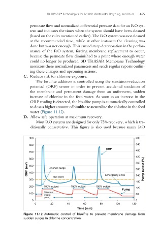
C. Reduce risk for chlorine exposure.
The bisulfite addition is controlled using the oxidation-reduction
potential (ORP) sensor in order to prevent accidental oxidation of
the membrane and permanent damage from an unforeseen, sudden
increase of chlorine in the feed water. As soon as an increase in the
ORP reading is detected, the bisulfite pump is automatically controlled
to dose a higher amount of bisulfite to neutralize the chlorine in the feed
water (Figure 11.12).
D. Allow safe operation at maximum recovery.
Most RO systems are designed for only 75% recovery, which is tra-
ditionally conservative. This figure is also used because many RO
900 600
800 540
ORP
700 480
420
600 360
ORP (mV) 500 Chlorine surge 300 Pump output (%)
400
Set point Emergency ends 240
300
180
200 100% output 100% output 100% output 120
Pump
Minimum
100 60
output
(40%)
0 0
0 20 40 60 80 100 120
Time (min)
Figure 11.12 Automatic control of bisulfite to prevent membrane damage from
sudden surges in chlorine concentration.