
Page 391 - Integrated Wireless Propagation Models
P. 391
t
T h e l e e C o m p r e h e n s i v e M o d e - 1 I n e g r a t i o n o f t h e T h r e e l e e M o d e I s 369
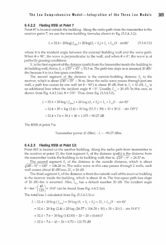
6.4.2.2 Finding RSSI at Point 7
Point #7 is located outside the building. Along the radio path from the transmitter to the
receiver point 7, we use the inter-building formulas shown in Eq. (5.3.4 .. 3.2):
(5.3.4.3.2)
where 8 is the incident angle between the external building wall and the wave path.
When e = 90°, the wave is perpendicular to the wall, and when 8 = 0°, the wave is at
perfectly grazing conditions.
5 1 is the first segment of the distance (path) from the transmitter inside the building to
2
{./ 2
its building wall, that is, 51 = 25 + 45 = 51.5 m. The path-loss slope m is assumed 20 dB/
dec because it is in a free space condition.
The second segment of the distance is the outside-building distance 5 to the
2
2
2
receiver, which is about {./ 30 + 25 = 39 m. Since the radio wave passes through just one
wall, a path loss causes by one wall (at 8 = 90°) is about 10 dB, that is, L , = 10 dB. Lee is
an additional loss when the incident angle 8 = 0°. Usually, Lee = 20 dB. In this case, as
shown from Fig. 6.4.2. ( a), e = 135°. Thus, from Eq. (5.3.4.3.2),
1
+ 20 log (51 + 5 ) + Le + L (1 - sin 8) 2
L = 32.4 + 20 log (J GHz) 2 c,
= 32.4 + 20 x log (2.4) + 20 log (51 . 5 + 39) + 10 + 20 (1 - sin 135°) 2
= 32.4 + 7.6 + 39 1 + 10 + . 1 7 5 = 90.27 dB
.
1
The RSSI at point 7 is
Transmitter power (0 dBm) - L = -90.27 dBm
6.4.2.3 Finding RSSI at Point 13:
Point #13 is located in the another building. Along the radio path from transmitter to
the receiver at point 13, the first segment 5 1 of the distance (path) is the distance from
2 2
the transmitter inside the building to its building wall, that is, {./ 25 + 9 = 26.57 m.
The second segment 5 of the distance is the outside distance, which is about
2
2
2
�( 45- 9) + 100 = 106.28 m. The radio wave in this case passes through 2 walls, each
wall causes about 10 dB loss, 2L , = 20 dB
The third segment 5 of the distance is from the outside wall of the receiver building
3
to the receiver inside the building, which is about 10 m. The free-space path-loss slope
of 20 dB/dec is assumed. Also, LGe has a default number 20 dB. The incident angle
1
e = tan- ( �) = 19.8° can be found from Fig. 6.4.2.1(a).
1 5
The total loss L calculated from Eq. (5.3.4.3.3) is
L = 32.4 + 20 log (J GHJ + 20 log (5 1 + 5 + 5) + 2L , + L (1 - sin 8) 2
c,
2
= 32.4 + 20 log (2.4) + 20 log (26.57 + 106.28 + 10) + 20 + 20 (1 - sin 19.8°) 2
= 32.4 + 7.6 + 20 log (142.85) + 20 + 20 x (0.661) 2
= 32.4 + 7.6 + 43 + 20 + 8.73 = 111.73 dB