Page 387 - Integrated Wireless Propagation Models
P. 387

T h e   l e e   C o m  p r e h e n s i v e   M  o d e l -  I n t e g r a t i o n   o f   t h e   T h r e e   l e e   M  o d e l s    365


                                                                     From Macrocell BS
                                                                      1  mile
                                                                     intercept
               From picocell BS                                      /
                                                   From microcell BS      I
                                                            �

                                                     Microcell     I    Macrocell
                                                                  I
                I n   building                                                      Cii
                                                                                    c
                                                                I                   0)
                         ioutside buildingi                    I                    ·u;
                                                                                    "0
                         �           :                                              Q)
            Cii                                                                     >
            c                                      :outside and                     'Qi
            0)                                                                      ()
                                                                                    Q)
            ·u;                      :building j   :  I n side                      a:
            "0
            Q)                                     j  building
            >
            'Qi
            ()
            Q)
            a:
                                                         I
                                                         I
              ------------------- ..  ------------------!-- ---�------  ------------� --------L -------------
                         ,           I   I         I
                         I           I   I         I
                         I           I   I         I
                         I           I   I         I
                         I           I   I         I
                         I           I   I         I
                         I           I   I         I
                         I           I   I         I
              14----__.P_=opell re ion   :   :   M i cr6cell r,egion   Macrocell region
                                                   A
                                                         �---
                                                                    1 . 5 km
                                                               ...
                                                  500 m
                                                   e
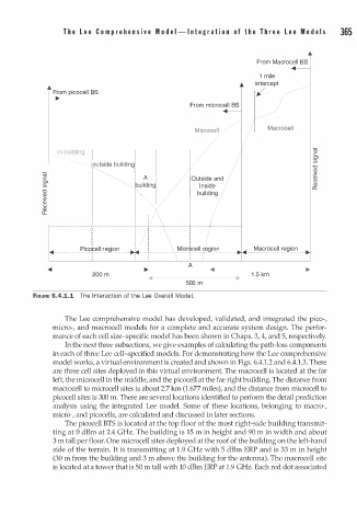
          FIGURE 6.4.1.1  The  n teraction of the Lee Over l l   Mod l .
                                             a
                          I
                  The Lee comprehensive model has developed, validated, and integrated the pico-,
               micro-, and macrocell models for a complete and accurate system design. The perfor­
               mance of each cell size-specific model has been shown in Chaps. 3, 4, and 5, respectively.
                  In the next three subsections, we give examples of calculating the path-loss components
               in each of three Lee cell-specified models. For demonstrating how the Lee comprehensive
               model works, a virtual environment is created and shown in Figs. 6.4.1.2 and 6.4. . 3. There
                                                                                1
               are three cell sites deployed in this virtual environment. The macrocell is located at the far
               left, the microcell in the middle, and the picocell at the far-right building. The distance from
               macrocell to microcell sites is about 2.7 km (1.677 miles), and the distance from microcell to
               picocell sites is 300 m. There are several locations identified to perform the detail prediction
               analysis using the integrated Lee model. Some of these locations, belonging to macro-,
               micro-, and picocells, are calculated and discussed in later sections.
                  The picocell BTS is located at the top floor of the most right-side building transmit­
               ting at 0 dBm at 2.4 GHz. The building is 15 m in height and 90 m in width and about
               3 m   tall per floor. One microcell sites deployed at the roof of the building on the left-hand
               side of the terrain. It is transmitting at  . 9 GHz with 5 dBm ERP and is 33 m in height
                                                1
               (30 m from the building and  m 3    above the building for the antenna .   The macrocell site
                                                                       )
                                                             1
               is located at a tower that is 50 m tall with 10 dBm ERP at  . 9 GHz. Each red dot associated
   382   383   384   385   386   387   388   389   390   391   392