Page 389 - Integrated Wireless Propagation Models
P. 389

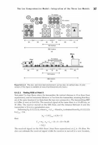
T h e   l e e   C o m  p r e h e n s i v e   M  o d e l -  I n t e g r a t i o n   o f   t h e   T h r e e   l e e   M  o d e l s    367


                                                                       Micro
                                                                        •    90


                         (      )  E     )        �  �                     )
                            50       50      50    1 5    35   60       40
                                               1 0 0 meters
                                               300 meters
                                                  (a)
                                                                     Micro
                                                                      •
                                                  75 meters
                              Pi co
                     1 5�                                             LJ


                                                  �  �                (     )
                            50      50       50    1 5    35    60      40
                                               1 0 0 meters

                                               300 meters
                                                  (b)
               FIGURE 6.4.1.3  The pico- and micro-test environment. (a) top view. (b) vertical view. (A color
                                                        l
               version of this figure is available at www.mhprofessiona . c omjiwpm. )

               6.4.2. 1    Finding RSSI  t   Point 5
                                   a
               Test point 5 is four floors above the transmitter. Its vertical distance is 12 m (four floor
               separations), and its horizontal distance is 0 m from the transmitter, meaning that they
               are at the same location if we look from the top-view perspective. The transmitting ERP
               is 0 dBm (1 mw) at 2.4 GHz. The received signal at the same floor is a 10-dB loss, or
               10  dBm. The receiver moved on the fifth floor, and the distance between it and the
               transmitter is 14 m in a penetration area.
                  Following Eq. (5.3.2.2.2.1), where n{; = 4 , L , = lOand m fl is obtained from Eq. (5.3.2.2.2.2)
                                                    1
                                               1
               for  f cHz  = 2.4,
                                         m fl = 1 . 93  f GHz + 6.36 = 11
               then
                                                             = 5
                                    L' = m fl  ·  n{; 1  + L  ,_ = 11 x 4 + 10  4 dB
                                      ;1
                                                  1
                                       = L (d )
                                           0
               The received signal on the fifth floor ( four floor separations) at d is -54 dbm. We
                                                                         0
               also can estimate the received signal while the receiver is moved to a new location,
   384   385   386   387   388   389   390   391   392   393   394