
Page 386 - Integrated Wireless Propagation Models
P. 386
364 C h a p t e r S i x
-20
-1 8
-1 6
-14
ii)
:s. -12
Ui
::J
i5' -1 0
ctl
c -8
"Cii
CJ -6
-4
-2
0
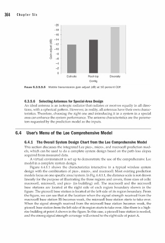
Cell-site Roof-top Diversity
Config
FIGURE 6.3.5.5.6 Mobile transmission gai n adjust (dB) at 50 percent CDF.
6.3.5.6 Selecting Antennas for Special-Area Design
An ideal antenna is an isotropic radiator that radiates or receives equally in all direc
tions, with a spherical pattern. However, in reality, all antennas have their own charac
teristics. Therefore, choosing the right one and introducing it in a system in a special
area can enhance the system performance. The antenna characteristics are the parame
ters requested by the prediction model as the inputs.
6.4 User's Menu of the Lee Comprehensive Model
6.4.1 The Overall System Design Chart from the Lee Comprehensive Model
This section discusses the integrated Lee pico-, micro-, and macrocell prediction mod
els, which can be used to do a complete system design based on the path-loss slopes
acquired from measured data.
A virtual environment is set up to demonstrate the use of the comprehensive Lee
model in a complete system design.
Figure 6.4.1.1 shows the characteristics interactive in a typical wireless system
design with the combination of pico-, micro-, and macrocell. Most existing prediction
models focus on one specific area/ system. In Fig. 6.4.1.1, the distance scale is not drawn
linearly for the purpose of illustrating the three regions and covers, three sizes of cells:
macrocell, microcell, and pico- (in-building) cell. The macrocell and the microcell
base stations are located at the right side of each region boundary shown in the
figure. The picocell base station is located at the left side of its region boundary. From
the figure, we can see that at the location when the signal strength received from the
macrocell base station BS becomes weak, the microcell base station starts to take over.
When the signal strength received from the microcell base station becomes weak, the
picocell base station from the left side of its region starts to take over. Also there is a high
rise building at point A shown in the figure. In this case, a picocell base station is needed,
and the strong signal strength coverage will extend to the right side of point A.