
Page 244 - System on Package_ Miniaturization of the Entire System
P. 244
218 Cha pte r F o u r
Amps/Meter
25
23
21
20
−1
18 1 2
−1 −4
16
4
3
14 −4
12
11
8.9
7.1
5.4
3.6
Jumpers
1.8
0.0
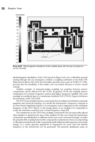
FIGURE 4.63 Electromagnetic simulations of the unstable layout with the use of jumpers for
current rerouting.
electromagnetic simulation of the LNA layout in Figure 4.63, now with better ground
routing through the use of jumpers, exhibits a coupling coefficient of less than 0.05.
Measured results for this LNA showed stable operation and a gain of 12 dB at 2.1 GHz,
proving that the instability in the earlier case was indeed because of return current
routing.
Another example of analog-to-analog coupling (or coupling between passive
components) can be observed in the VCOs. In general, VCOs use multiple passive
components for accurate frequency control and higher frequency stability. One such
example is considered here of a transformer-feedback VCO (TVCO). Figure 4.64 shows
the schematic of the TVCO [50].
The TVCO uses multiple passive components that are subject to both intercomponent
magnetic and electrical coupling. As a result, the transformer’s frequency response in
its out-of-band (stopband) region is of consequence and is important in the oscillation
frequency of the VCO. Hence, in the design phase of an oscillator it is important to
verify the oscillation condition over a broad frequency range [50].
The transformer in the TVCO has multiple components that are physically placed
close together to minimize the area of the oscillator. In the case where the transformer
components are distributed on different metal layers and connected through via-holes
the parasitic EM coupling between the components is minimized. However, depending
on the physical placement of the components, both inductors and capacitors can couple
energy. As a result, parasitic passbands at frequencies far away from the desired
frequency in the transformer can be generated. The parasitic passbands cause an