
Page 249 - System on Package_ Miniaturization of the Entire System
P. 249
Mixed-Signal (SOP) Design 223
electromagnetic bandgap (EBG) structures, which are periodic patterns on the power-
ground planes. EBGs generally provide better isolation and do not require any additional
components. This is described in a later section.
In this section, various coupling mechanisms through the power-ground planes
between the digital and analog domains are presented. These include coupling through
the splits as well as horizontal and vertical coupling between the power-ground planes.
Split Planes
Split power and/or ground planes (with the use of multiple power supplies) have been
applied for isolating the various regions of the power-ground planes [61]. However
part of the electromagnetic energy can still couple through the gap, especially at higher
frequencies [62]. There is increased coupling at the resonant frequencies of the split
planes. Hence, this method only provides marginal isolation (–20 to approximately –60 dB)
at frequencies above 1 GHz and becomes ineffective as system operating frequencies
increase. With the high sensitivity requirements of long-distance communication
protocols (–102 dBm for GSM900, –116 dBm for WCDMA), the system-level isolation
requirements are much higher. Further, as systems become more and more compact,
multiple power supplies also become a luxury that the designer cannot afford.
With the restriction to use a single power supply for both digital and RF circuits, the
need for a low-pass functional block that provides dc connectivity throughout the
system but prevents the transfer of high-frequency noise components arises. In such a
scenario, the analog/RF and digital subsystems would be powered using separate
sections of a common power distribution system (power planes), with the filter blocking
transfer of high-frequency signal power between the sections. Several schemes involving
split power planes connected using a lumped inductor, a printed inductor, or a ferrite
bead have been suggested [63–64]. However, all of them offer maximum isolation in the
order of –40 dB, with significantly lower isolation numbers at resonant frequencies of
the discrete components.
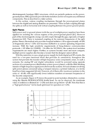
As an example, Figure 4.70 shows the point-to-point isolation obtained in a system
using the Murata BLM18GG471SN1 ferrite bead. As can be observed, the maximum
value of isolation is obtained at ∼1 GHz and does not go below –25 dB. Note that this is
a “high-performance” ferrite bead optimized for operation at 1 GHz.
–5
Isolation (dB) dB(S8, 7) –15
–10
–20
–25
–30
0 1 2 3 4 5 6
Freq, GHz
FIGURE 4.70 Isolation of a ferrite bead.