
Page 250 - System on Package_ Miniaturization of the Entire System
P. 250
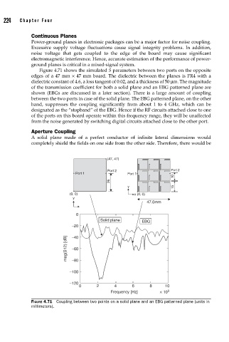
224    Cha pte r  F o u r


                    Continuous Planes
                    Power-ground planes in electronic packages can be a major factor for noise coupling.
                    Excessive supply voltage fluctuations cause signal integrity problems. In addition,
                    noise voltage that gets coupled to the edge of the board may cause significant
                    electromagnetic interference. Hence, accurate estimation of the performance of power-
                    ground planes is critical in a mixed-signal system.
                       Figure 4.71 shows the simulated S parameters between two ports on the opposite
                    edges of a 47 mm × 47 mm board. The dielectric between the planes is FR4 with a
                    dielectric constant of 4.6, a loss tangent of 0.02, and a thickness of 50 μm. The magnitude
                    of the transmission coefficient for both a solid plane and an EBG patterned plane are
                    shown (EBGs are discussed in a later section). There is a large amount of coupling
                    between the two ports in case of the solid plane. The EBG patterned plane, on the other
                    hand, suppresses the coupling significantly from about 1 to 4 GHz, which can be
                    designated as the “stopband” of the EBG. Hence if the RF circuits attached close to one
                    of the ports on this board operate within this frequency range, they will be unaffected
                    from the noise generated by switching digital circuits attached close to the other port.

                    Aperture Coupling
                    A solid plane made of a perfect conductor of infinite lateral dimensions would
                    completely shield the fields on one side from the other side. Therefore, there would be


                                                   (47, 47)

                                                   Port 2                    Port 2
                                      Port 1               Port 1
                                                                              10
                                                    26
                                                           y                  15
                                    (0, 0)                    x  (0, 0)
                                     y
                                                                   47.0mm

                                      0
                                                Solid plane      EBG
                                     −20

                                  mag(S12) [dB]  −40

                                     −60

                                     −80
                                    −100

                                    −120
                                       0       2      4      6      8     10
                                                    Frequency [Hz]      × 10 9
                    FIGURE 4.71  Coupling between two points on a solid plane and an EBG patterned plane (units in
                    millimeters).