Page 247 - System on Package_ Miniaturization of the Entire System
P. 247

Mixed-Signal (SOP) Design   221


                              The EM coupling between resonator elements of TVCO2 can be reduced by
                           separating the components (especially C  and L ) spatially in the planar direction
                                                            2
                                                                  2
                           or by moving from microstrip- to stripline-type designs. Hence, on comparing
                           the results for TVCO1 and TVCO2 it can be concluded that 3D separation of the
                           resonator elements on multiple LCP layers reduces both the undesired EM
                           coupling and VCO size.
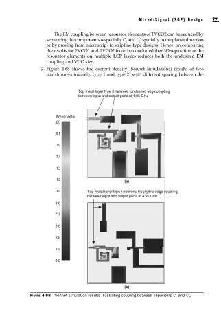
                         2.  Figure 4.68 shows the current density (Sonnet simulations) results of two
                           transformers (namely, type 1 and type 2) with different spacing between the


                                        Top metal layer type II network: Undesired edge coupling
                                        between input and output ports at 4.95 GHz


                               Amps/Meter
                                            2
                               23
                                            1
                               21

                               19

                               17

                               15

                               13
                                                            (a)
                               12           Top metal layer type I network: Negligible edge coupling
                                            between input and output ports at 4.95 GHz
                               9.6                 2

                               7.7

                               5.8

                               3.8

                               1.9

                               0.0


                                                            (b)
                    FIGURE 4.68  Sonnet simulation results illustrating coupling between capacitors C 1  and C m .
   242   243   244   245   246   247   248   249   250   251   252