
Page 260 - System on Package_ Miniaturization of the Entire System
P. 260
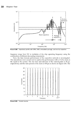
234    Cha pte r  F o u r


                           10 –1


                                                                                   On chip
                                                                                  capacitors
                           10 –2
                         Impedance (Ω)


                           10 –3
                                                       Board capacitors
                                                                          Package
                                                                         capacitors


                           10 –4
                             10 2          10 4           10 6          10 8          10 10
                                                     Frequency (Hz)
                    FIGURE 4.80  Impedance profi le with VRM, SMD, embedded package, and on-chip capacitor.

                    frequency range from DC to multiples of the chip operating frequency using the
                    combination of different decoupling components.
                       Next, the time domain performance of the capacitive network is investigated.
                    The simulations were carried out to capture the performance with a 2 GHz clock as
                    the input to the system. The rise time and fall time of the current pulse is 50 ps,
                    respectively, and the time period of the clock is 500 ps as shown in Figure 4.81. The


                                    40
                                    35

                                    30

                                    25
                                   Current(A)  20


                                    15
                                    10

                                    5
                                    0
                                        0      1     2     3     4     5     6 –9
                                                        Time(sec)           ×10
                    FIGURE 4.81  Current source.